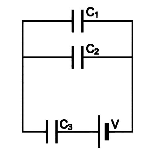
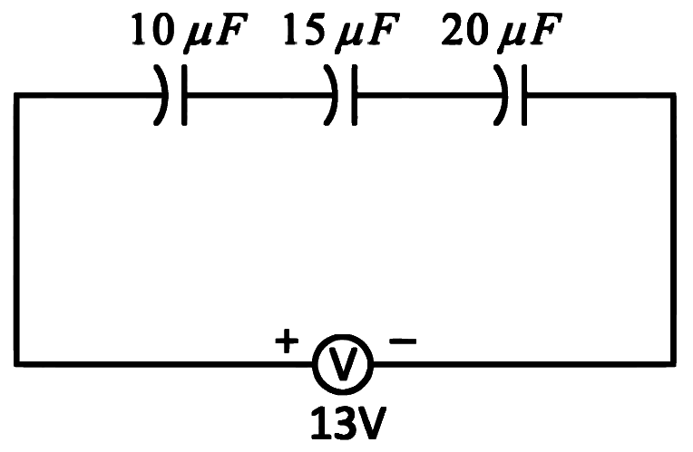
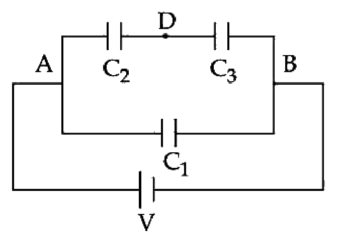
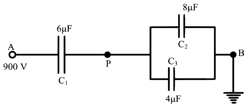
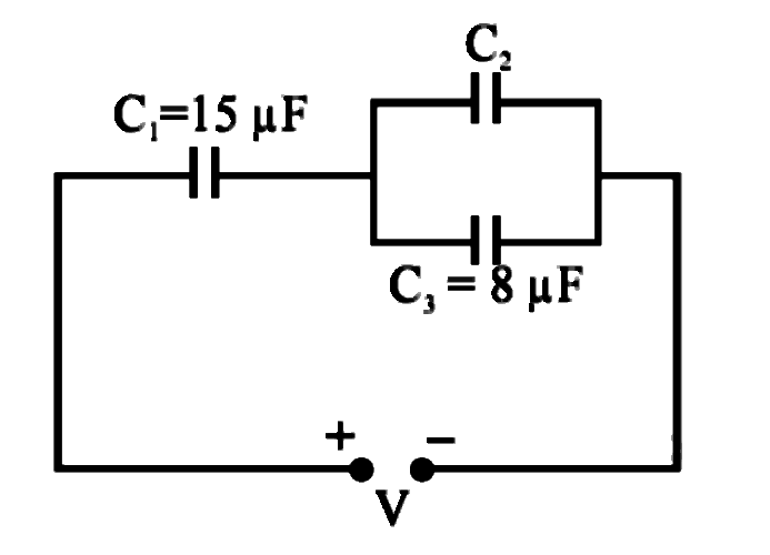
Capacitors of capacities C1 and C2 are connected in series. If the combination is connected to a supply of V volt then the potential difference across capacitor C2 is
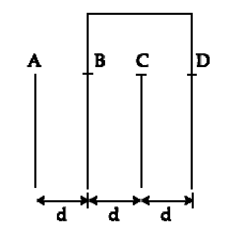
Four parallel plate capacitors are connected in parallel. Each capacitor has a plate area 4A and the separation between the plates is d,2d,3d and 4d respectively. The equivalent capacity of the combination is [ε0= permittivity of free space]
Two parallel plate air capacitors are connected in parallel. Each capacitor has plate area A/2 and separation between the plates is d and 2d respectively. The equivalent capacity of the combination is
Three parallel plate air capacitors are connected in parallel. Each capacitor has plate area A/3 and separation between the plates is d, 2d and 3d respectively. The equivalent capacity of the combination is (ϵ0-permittivity of free space)
Three identical capacitors connected in series have net capacitance 'x'. Then they are connected in parallel. The ratio of energy stored in series configuration to that in parallel configuration is (if both configurations are connected to the same source)
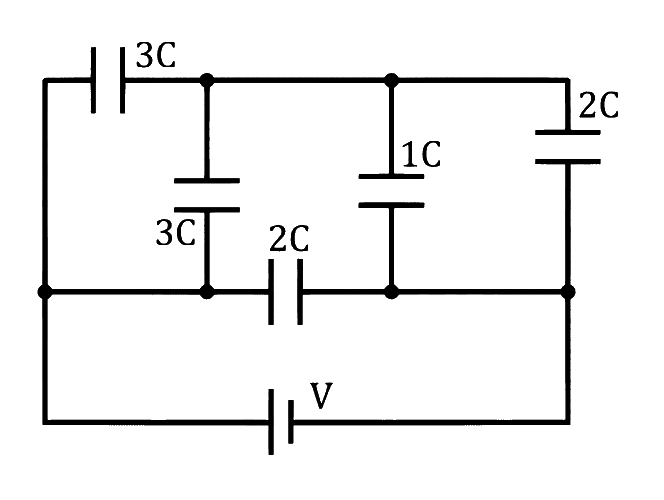
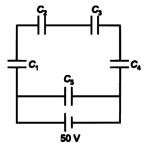
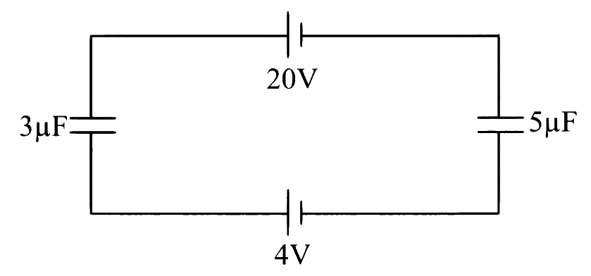
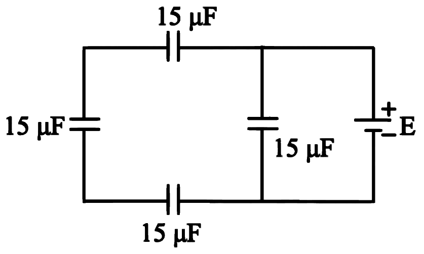
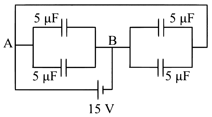
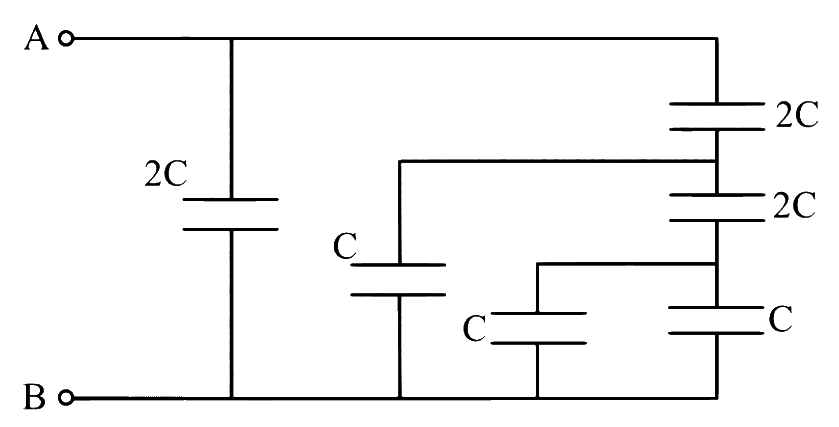
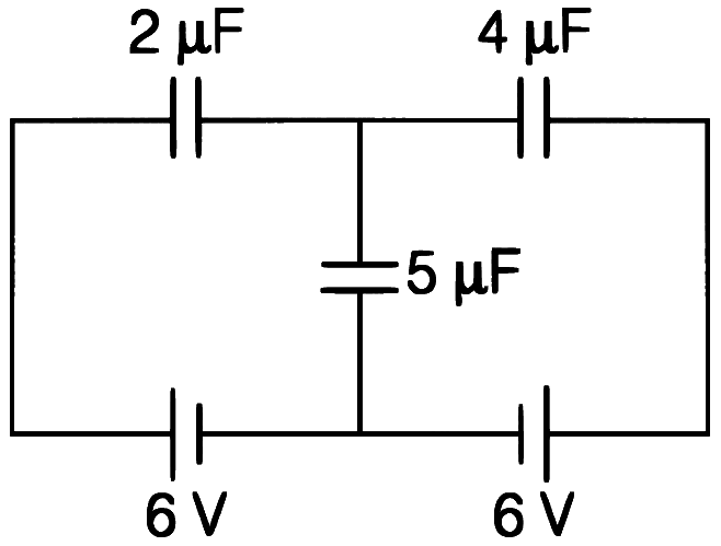
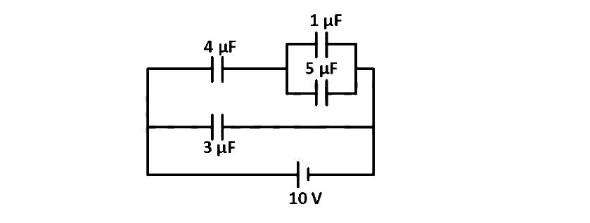
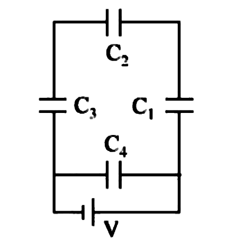
Figure shows a network of five capacitors connected to a supply voltage 'V'. The equivalent capacitance and the energy stored in the network is respectively
Two capacitors, C1 and C2 have their capacitances in the ratio 1:2. Vs and Vp are the potential differences applied across the series and parallel combination of C1 and C2 respectively, so that the energy stored in the two cases becomes same. The ratio Vs to Vp is
The potential difference that must be applied across the parallel and series combination of three identical capacitors such that the energy stored in them becomes the same. The ratio of potential difference in parallel to series combination is
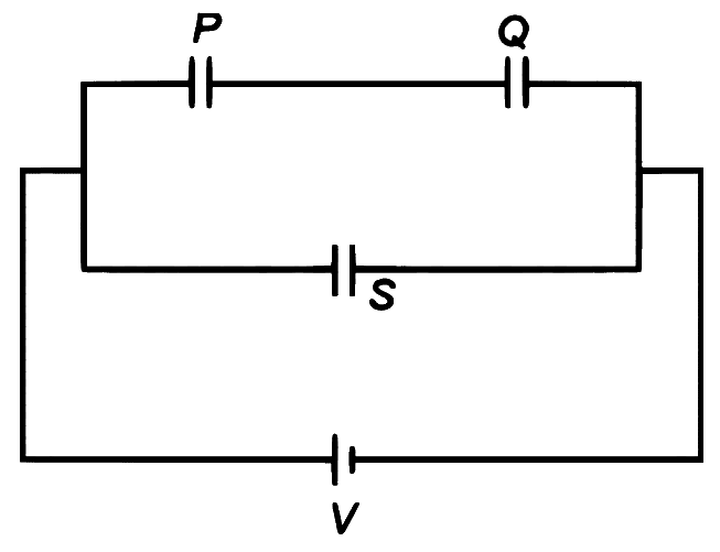
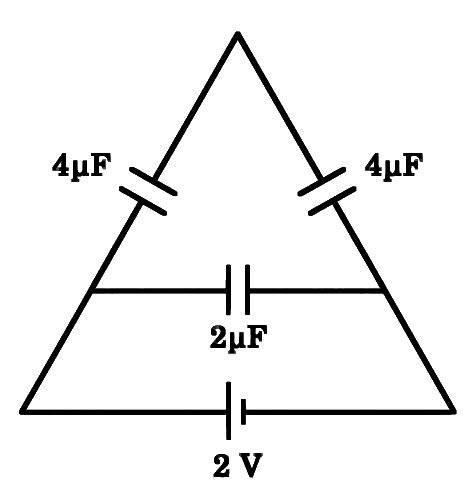
Three identical capacitors, P,Q and S, each of the capacitance C, are connected to a battery of voltage V, as shown in the figure. If the energy stored in the capacitor P and total energy stored in the system are UP and UT, respectively, then the ratio UTUP is:
Three capacitors each of capacitance ' C ' and breakdown voltage ' V ' are connected in series. The capacitance and breakdown voltage of the series combination will be respectively
A series combination of 10 capacitors, each of value ' C1 ' is charged by a source of potential difference ' 4 V '. When another parallel combination of 8 capacitors, each of value ' C2 ' is charged by a source of potential difference ' V ', it has the same total energy stored in it as in the first combination. The value of ' C2 ' is
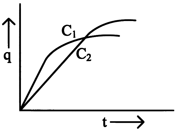
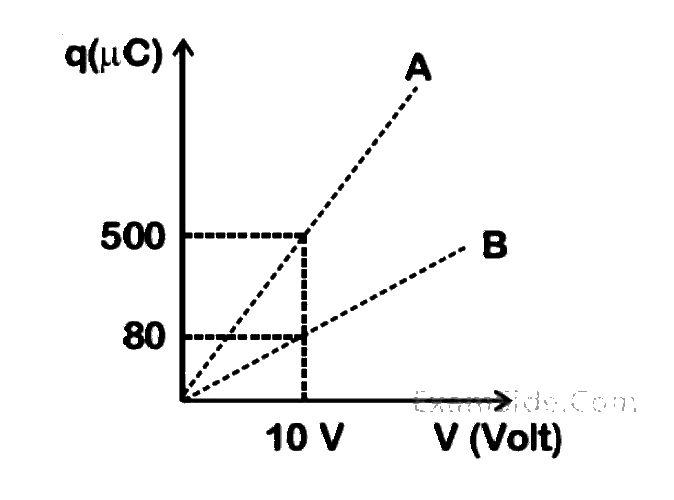
Two capacitors C1 and C2 are connected in parallel to a battery. Charge-time graph is shown below for the two capacitors. The energy stored with them are U1 and U2, respectively. Which of the given statements is true?
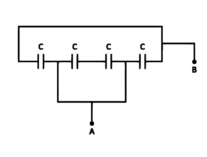
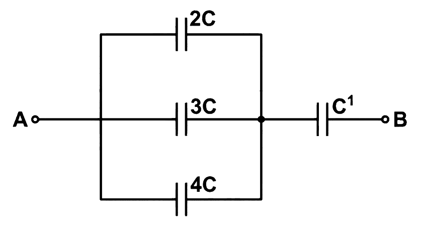
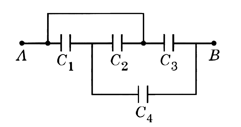
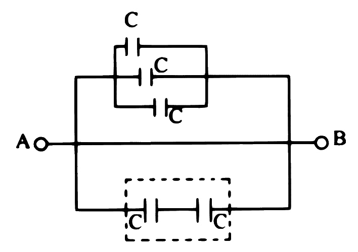
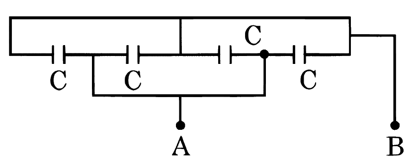
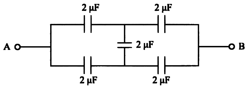
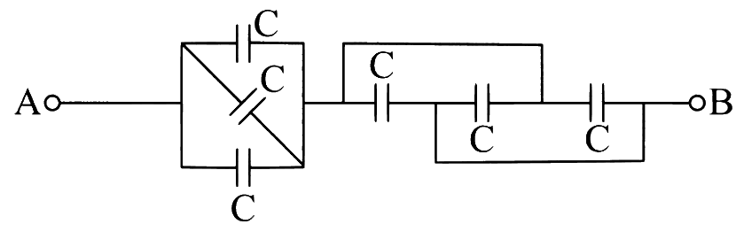
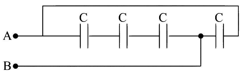
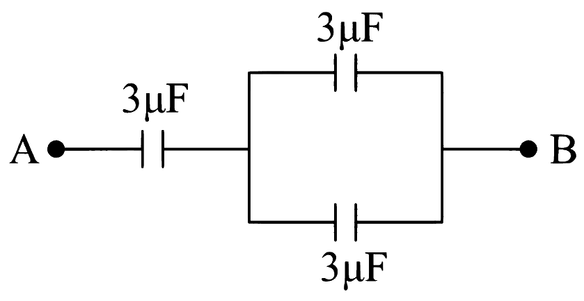
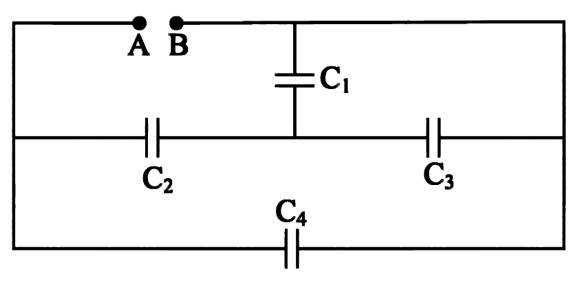
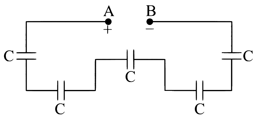
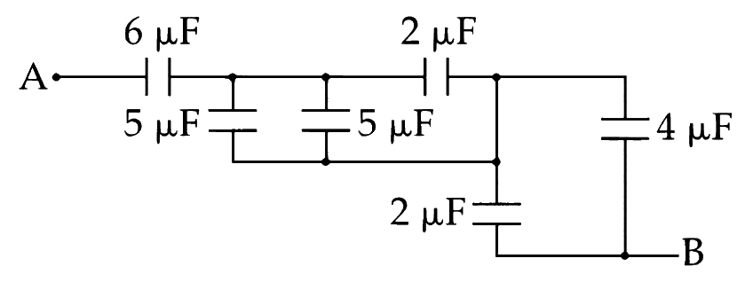
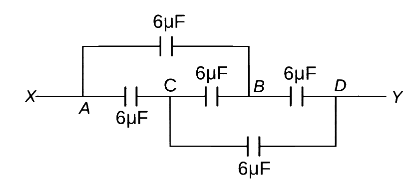
Five capacitors, each of capacity ' C ' are connected as shown in the figure. The resultant capacity between A and B is 14μF. The capacity of each capacitor is
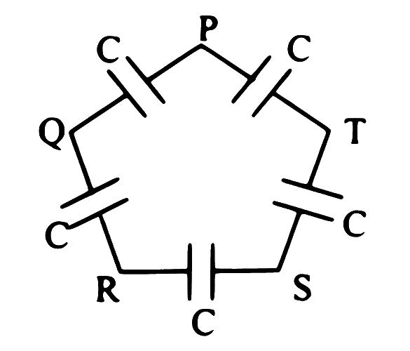
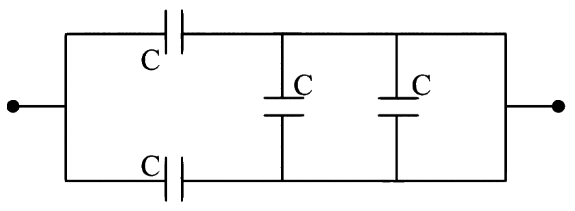
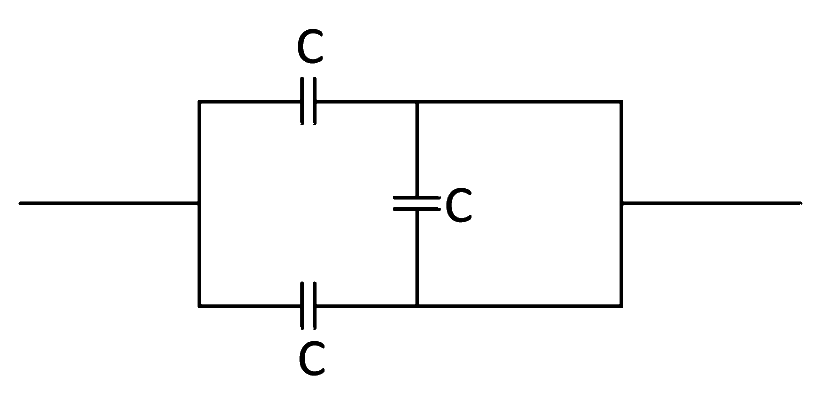
Five capacitors, each of capacitance ' C ' are connected as shown in the figure. The ratio of equivalent capacitance between P and R and the equivalent capacitance between P and Q is
Three condensers of capacities ' C1 ', ' C2 ', ' C3 ' are connected in series with a source of e.m.f. ' V '. The potentials across the three condensers are in the ratio
When three capacitors of equal capacities are connected in parallel and one of the same capacity, capacitor is connected in series with the combination. The resultant capacity is 4.5μF. The capacity of each capacitor is
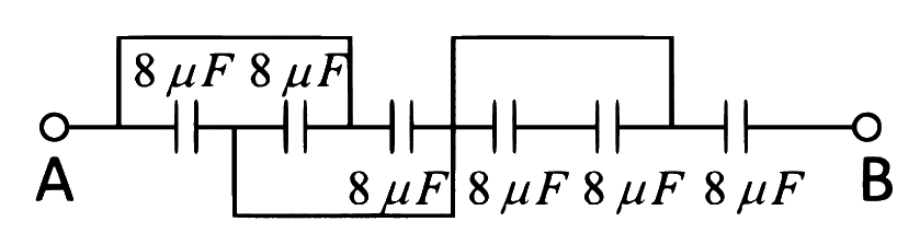
Seven capacitors each of capacitance 2μF are connected in a configuration to obtain an effective capacitance 136μF. The combination which will achieve this will have
A series combination of n1 capacitors, each of value C1 is charged by a source of potential difference 6 V. Another parallel combination of n2 capacitors, each of value C2 is charged by a source of potential difference 2 V. Total energy of both the combinations is same. The value of C2 in terms of C1 is
The potential difference that must be applied across the series and parallel combination of 4 identical capacitors is such that the energy stored in them becomes the same. The ratio of potential difference in series to parallel combination is
Three capacitors of capacitances 25μF,30μF and 45μF are connected in parallel to a supply of 100 V. Energy stored in the above combination is E. When these capacitors are connected in series to the same supply, the stored energy is x9E. The value of x is _________.
Numerical answer type. Work it out, then open the answer.
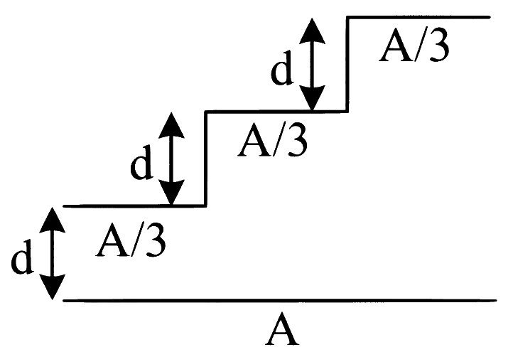
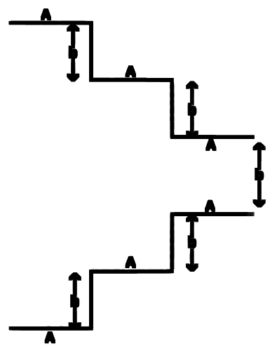
A capacitor is made of a flat plate of area A and a second plate having a stair-like structure as shown in figure. If the area of each stair is 3A and the height is d, the capacitance of the arrangement is:
Three identical capacitors of capacitance 'C' each are connected in series and this connection is connected in parallel with one more such identical capacitor. Then the capacitance of whole combination is
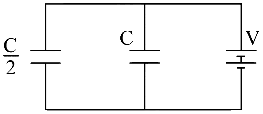
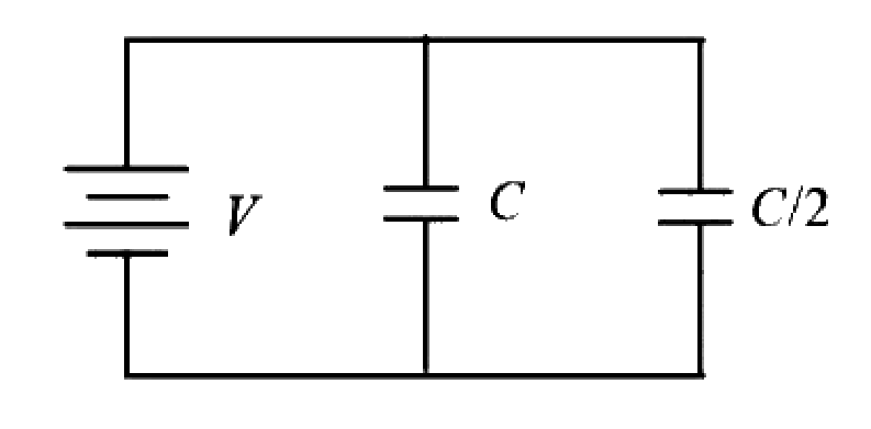
Two condensers one of capacity 2C and other capacity C are connected to a battery of voltage V as shown. The work done in charging fully both the condensers is
A parallel combination of two capacitors of capacities '2C' and 'C' is connected across 5 V battery. When they are fully charged, the charges and energies stored in them be 'Q1 ', 'Q2' and 'E1 ', 'E2' respectively. Then Q1−Q2E1−E2 in J/C is (capacity is in Farad, charge in Coulomb and energy in J)
The ratio of potential difference that must be applied across parallel and series combination of two capacitors C1 and C2 with their capacitance in the ratio 1:2 so that energy stored in these two cases becomes same is
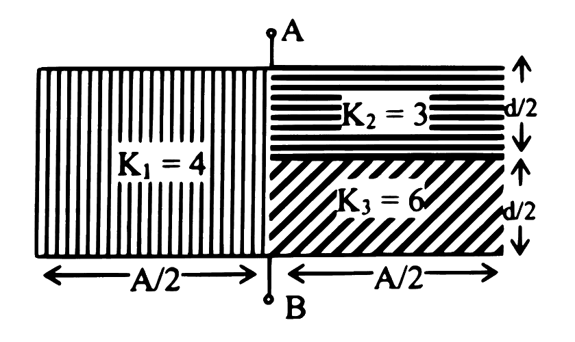
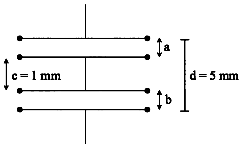
As shown in the figure, two parallel plate capacitors having equal plate area of 200 cm2 are joined in such a way that a=b. The equivalent capacitance of the combination is xϵ0 F. The value of x is ____________.
Numerical answer type. Work it out, then open the answer.
The effective capacitances of two capacitors are 3 μF and 16 μF, when they are connected in series and parallel respectively. The capacitance of two capacitors are:
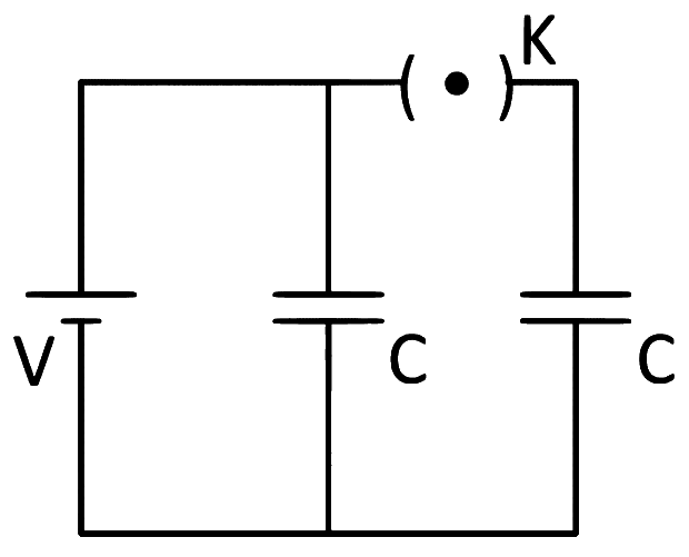
A source of potential difference V is connected to the combination of two identical capacitors as shown in the figure. When key 'K' is closed, the total energy stored across the combination is E1. Now key 'K' is opened and dielectric of dielectric constant 5 is introduced between the plates of the capacitors. The total energy stored across the combination is now E2. The ratio E1/E2 will be:
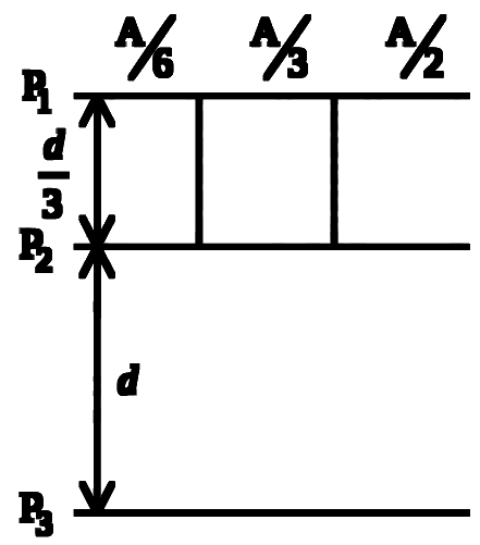
Combination of four parallel plate air capacitors is shown in figure. Separation between the plate P1 & P2 is 3d and separation between the plates P2 and P3 is d. The equivalent capacitance of the configuration is _______ μF.
(Given dϵ0A=4μF. Where A=Area of plates)
Numerical answer type. Work it out, then open the answer.
A parallel plate capacitor is made up of stair like structure with a plate area A of each stair and that is connected with a wire of length b, as shown in the figure. The capacitance of the arrangement is 15xbϵ0A. The value of x is ____________.
Numerical answer type. Work it out, then open the answer.
Capacitors of capacities C1,C2 and C3 are connected in series. If the combination is connected to a supply of 'V' volt, then potential difference across capacitor 'C1' is
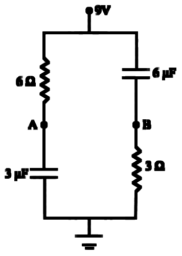
Three capacitors C1 = 2μF, C2 = 6μF and C3 = 12μF are connected as shown in figure. Find the ratio of the charges on capacitors C1, C2 and C3 respectively:
Consider the combination of 2 capacitors C1 and C2 with C2 > C1, when connected in parallel, the equivalent capacitance is 415 times the equivalent capacitance of the same connected in series. Calculate the ratio of capacitors, C1C2.
Four identical rectangular plates with length, l = 2 cm and breadth, b = 23 cm are arranged as shown in figure. The equivalent capacitance between A and C is dxε0. The value of x is ______________. (Round off to the Nearest Integer)
Numerical answer type. Work it out, then open the answer.
Two capacitors of capacities 2μF and 4μF are connected in parallel. A third capacitor of 6μF capacity is connected in series with this combination. A battery of 12 V is connected across this combination. The charge on 2μF capacitor is
Effective capacitance of parallel combination of two capacitors C1 and C2 is 10 μF. When these capacitors are individually connected to a voltage source of 1V, the energy stored in the capacitor C2 is 4 times that of C1. If these capacitors are connected in series, their effective capacitance will be:
Seven capacitors, each of capacitance 2 μF, are to be connected in a configuration to obtain an effective capacitance of (136)μF. Which of the combinations, shown in figures below, will achieve the desired value
A capacitance of 2 μF is required in an electrical circuit across a potential difference of 1.0 kV. A large number of 1 μF capacitors are available which can withstand a potential difference of not more than 300 V. The minimum number of capacitors required to achieve this is:
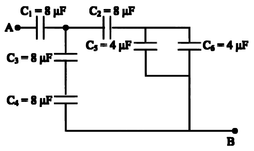
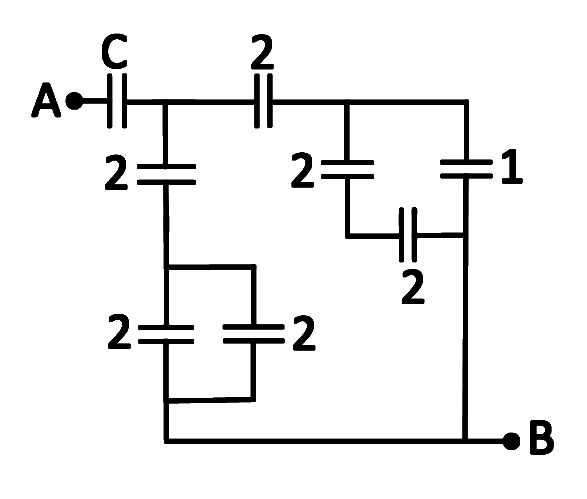
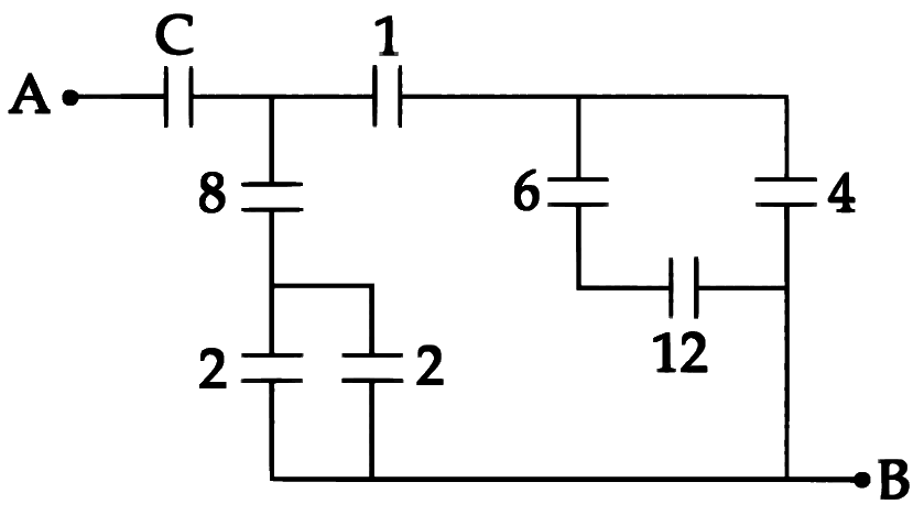
Figure shows a network of capacitors where the numbers indicates capacitances in micro Farad. The value of capacitance C if the equivalent capacitance between point A and B is to be 1 μF is:
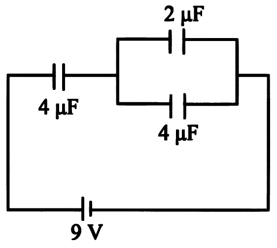
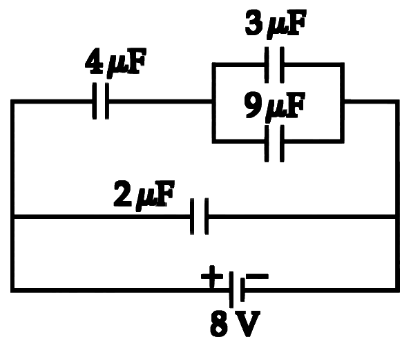
A combination of capacitors is set up as shown in the figure. The magnitude of the electric field, due to a point charge Q (having a charge equal to the sum of the charges on the 4μF and 9μF capacitors), at a point distance 30 m from it, would equal:
A series combination of n1 capacitors, each of value C1, is charged by a source of potential difference 4V. When another parallel combination of n2 capacitors, each of value C2, is charged by a source of potential difference V, it has the same (total) energy stored in it. as the first combination has. The value of C2. in terms of C1, is then
Three capacitors each of capacitance C and of breakdown voltage V are joined in series. The capacitance and breakdown voltages of the combination will be
Two condensers, one of capacity C and other of capacity C/2 are connected to a V-volt battery, as shown in the figure. The work done in charging fully both the condensers is
A parallel plate capacitor is made by stacking n equally spaced plates connected alternatively. If the capacitance between any two adjacent plates is C then the resultant capacitance is
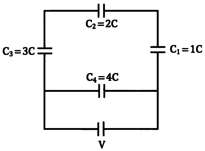
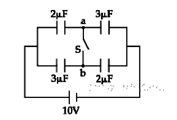
A network of four capacitors of capacity equal to C1 = C, C2 = 2C, C3 = 3C and C4 = 4C are connected to a battery as shown in the figure. The ratio of the charges on C2 and C4 is