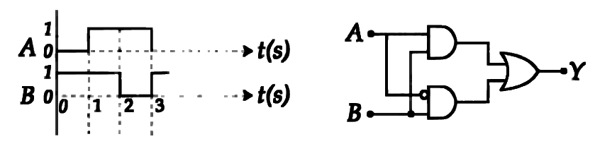
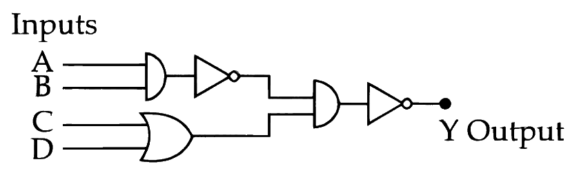
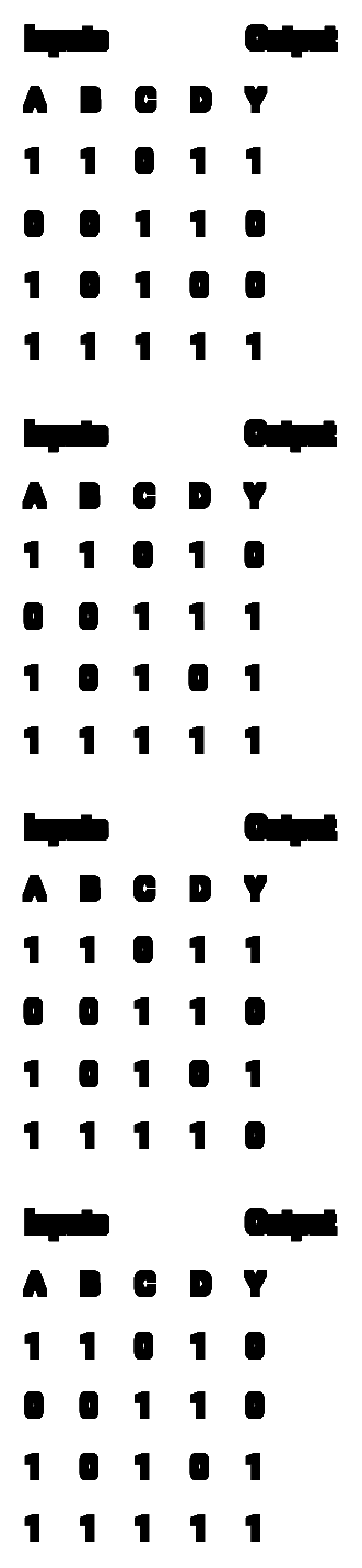
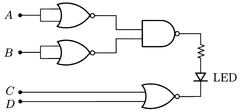
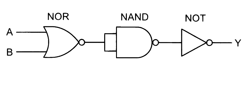
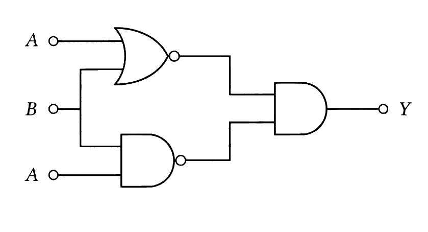
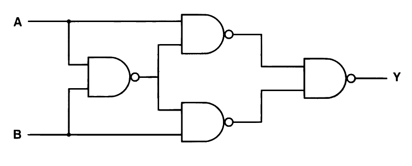
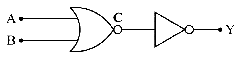
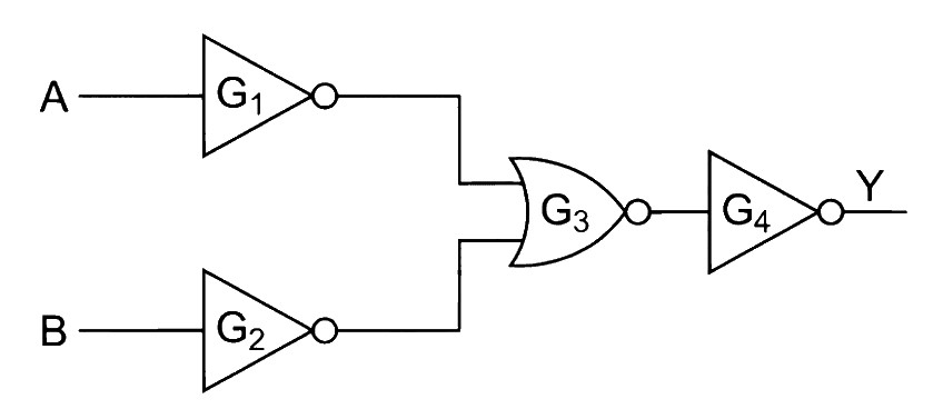
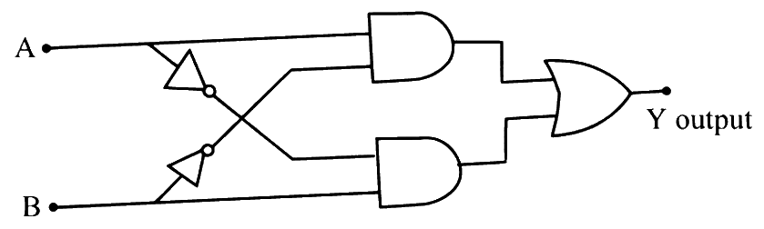
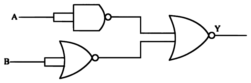
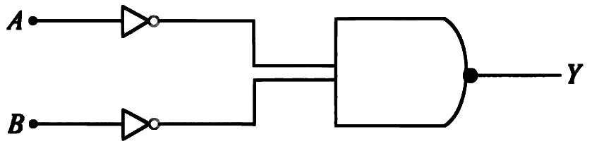
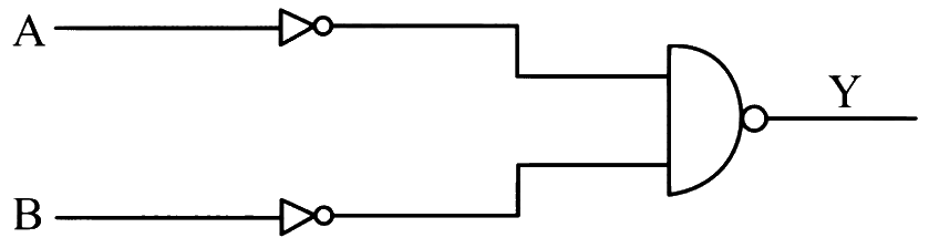
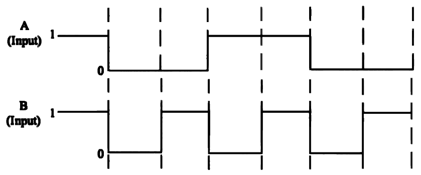
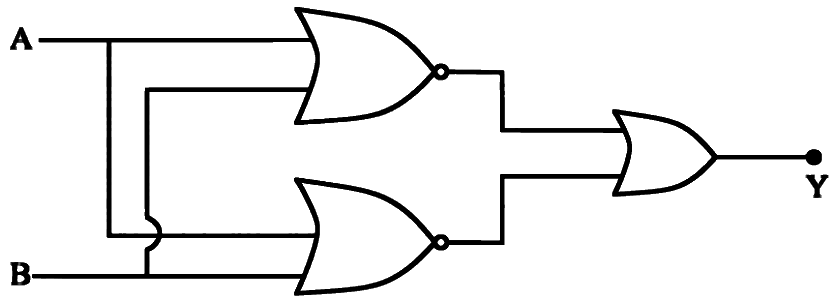
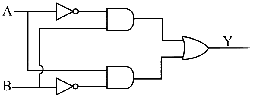
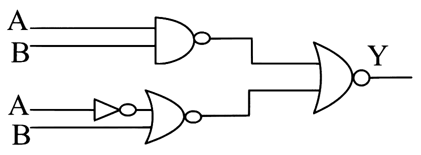
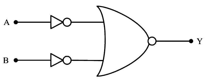
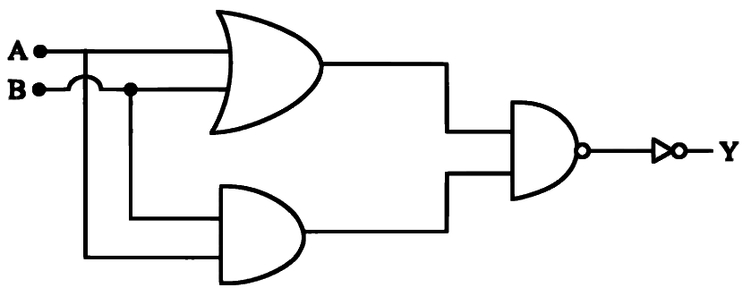
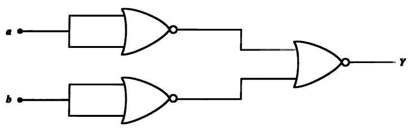
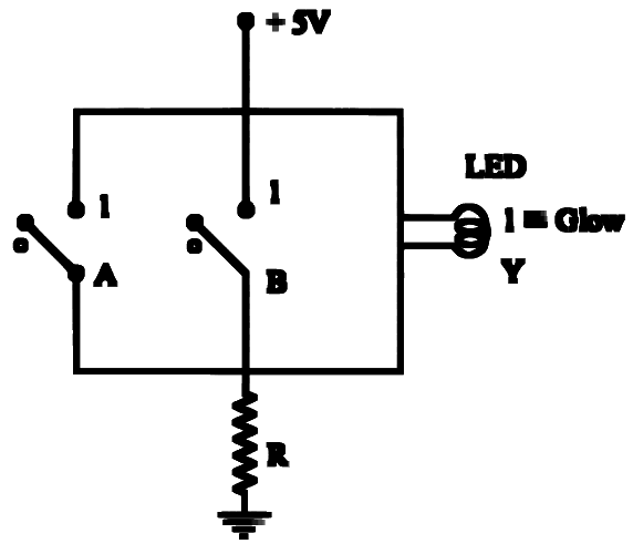
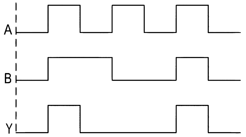
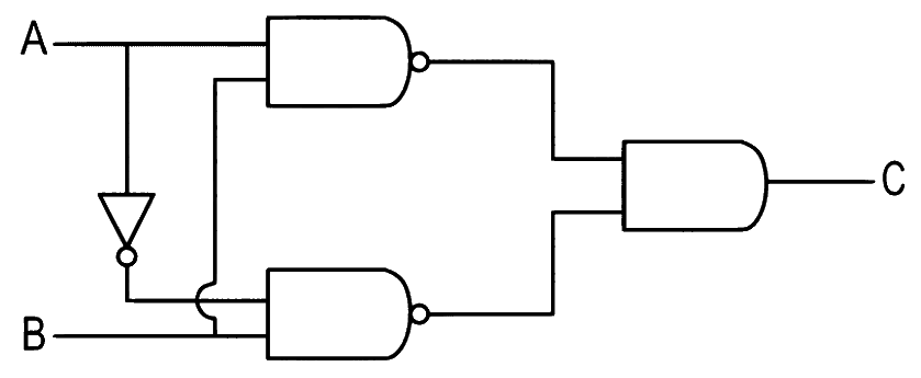
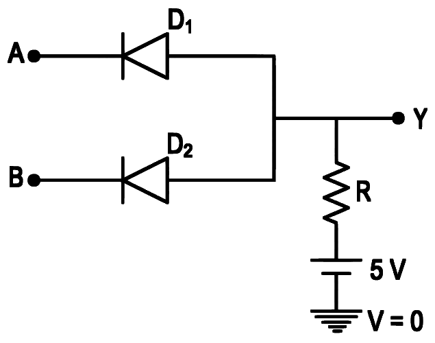
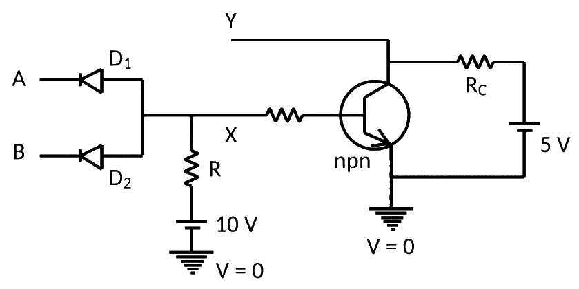
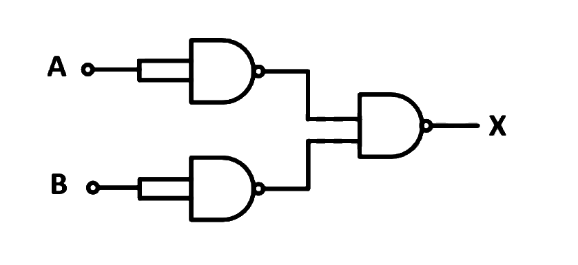
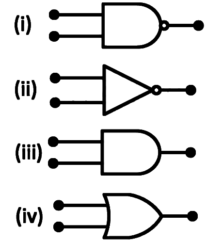
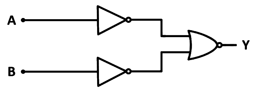
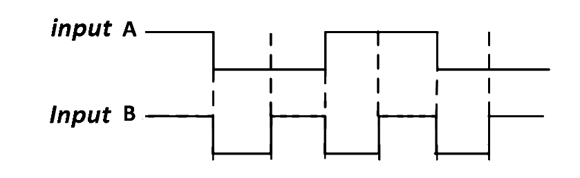
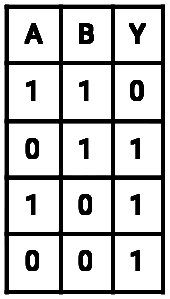
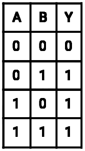
Q1 MHT CET 2026 · 20 MAY · SHIFT 1 Easy ☆
Logic Gates
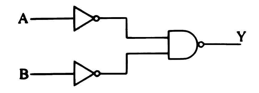
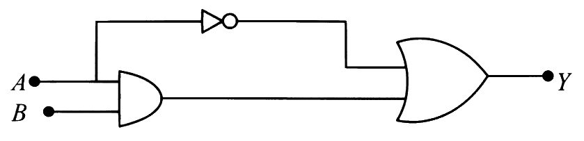
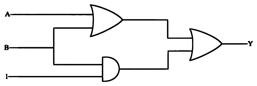
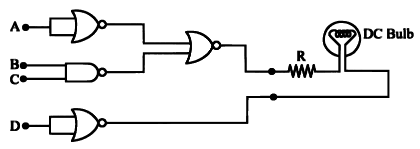
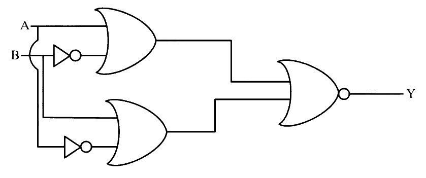
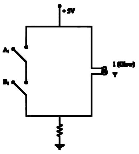
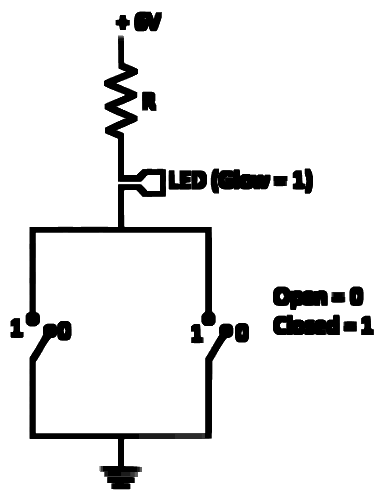
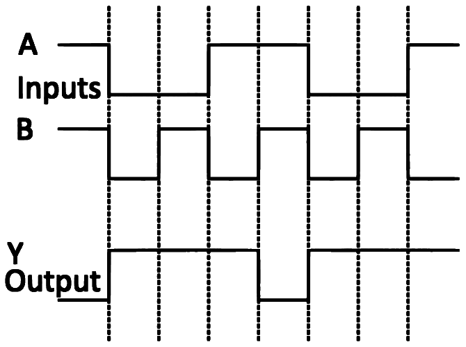
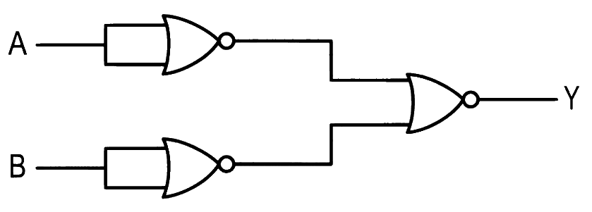
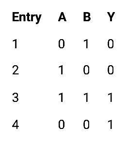
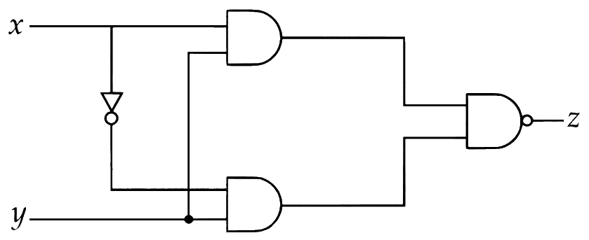
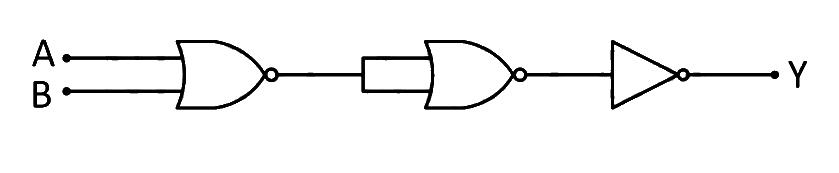
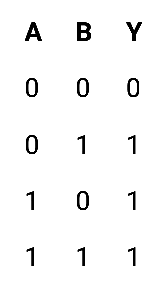
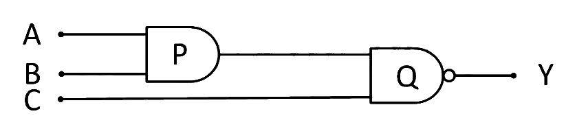
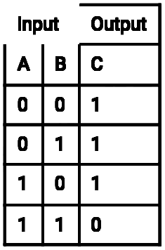
In a two input logic gate, when one input is '1' and the other is '0' (zero), the output is '1'. But even if both inputs are '0' (zero), the output is '1'. The logic gate is
(a) an AND gate. (b) an X-OR gate. (c) a NAND gate. (d) a NOR gate. Show answer and solution
Answer: (c)
Loading the solution…
Report a mistake Q2 MHT CET 2026 · 19 APR · SHIFT 1 Easy ☆
Logic Gates
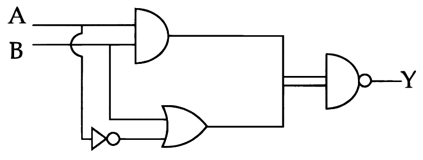
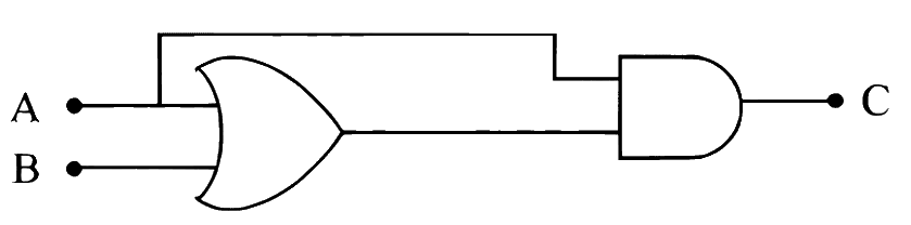
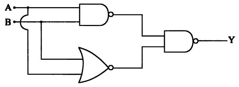
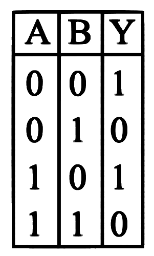
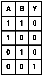
For a two input logic gate, when the inputs are 'zero' and 'zero' the output is 'one'. When the inputs are 'one' and 'zero' the output is 'zero'. The type of logic gate is
Show answer and solution
Answer: (c)
Loading the solution…
Report a mistake Q3 MHT CET 2026 · 18 APR · SHIFT 1 Easy ☆
Logic Gates
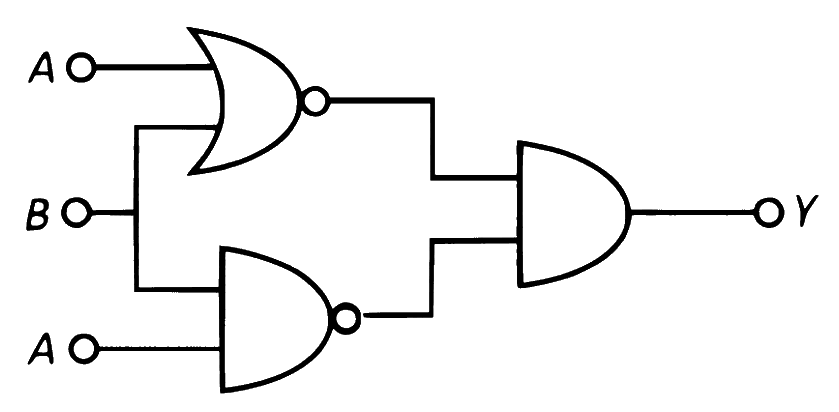
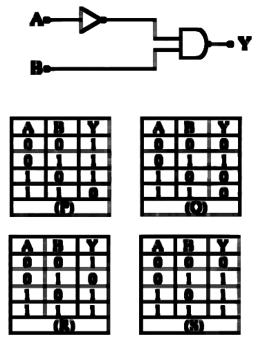
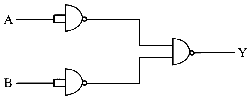
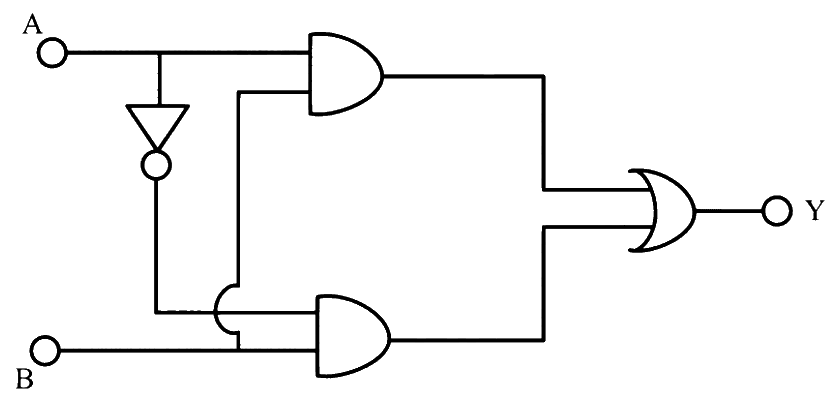
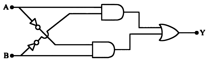
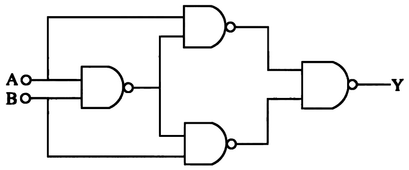
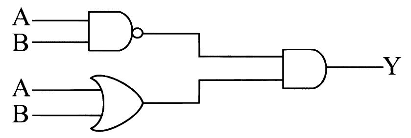
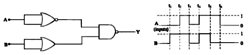
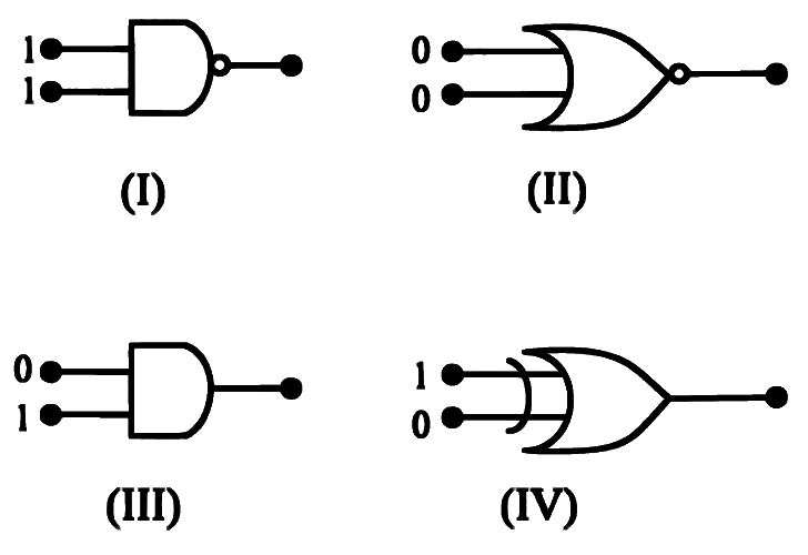
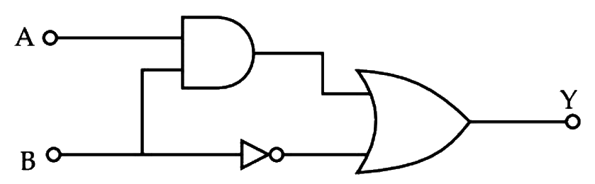
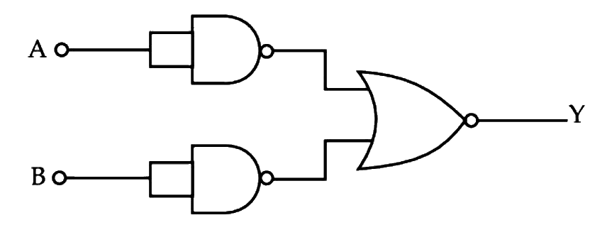
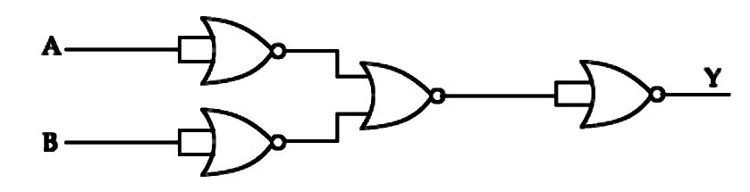
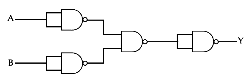
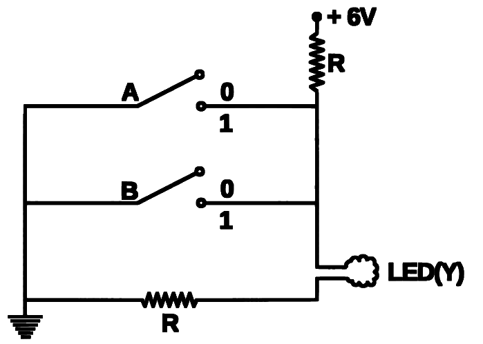
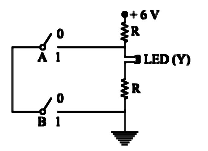
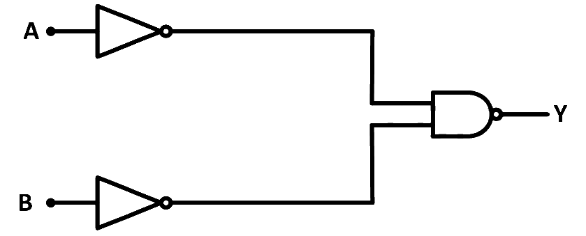
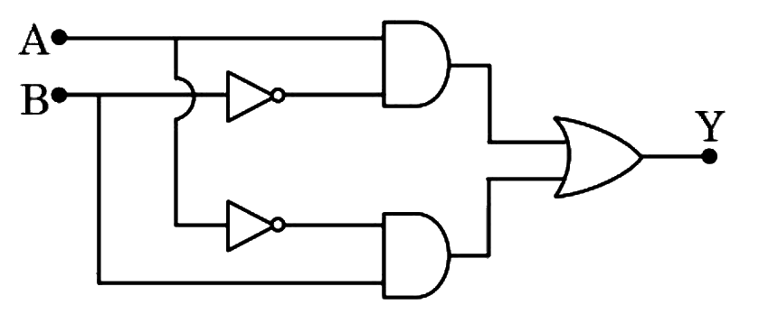
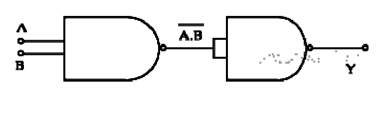
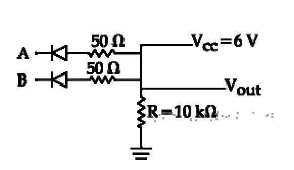
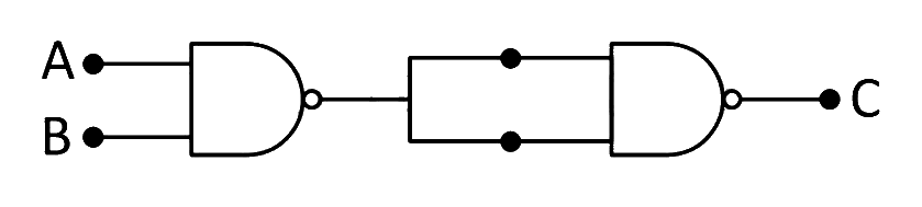
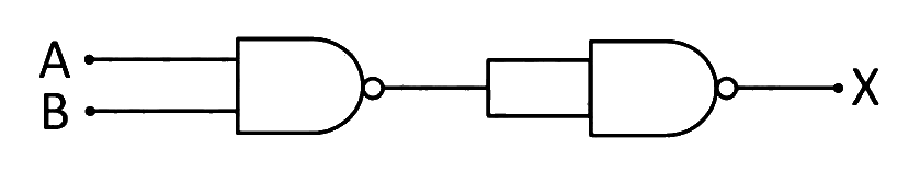
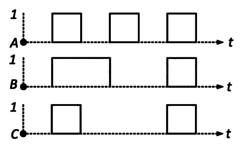
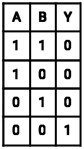
Which of the following logic gates will have an output of '1' (one) for the given inputs?
Show answer and solution
Answer: (b)
Loading the solution…
Report a mistake Q4 MHT CET 2026 · 19 MAY · SHIFT 1 Easy ☆
Logic Gates
If two inputs of a NOR gate are shorted, the resulting gate is
(a) a NAND gate. (b) an OR gate. (c) an AND gate. (d) a NOT gate. Show answer and solution
Answer: (d)
Loading the solution…
Report a mistake Q5 MHT CET 2026 · 15 MAY · SHIFT 2 Easy ☆
Logic Gates
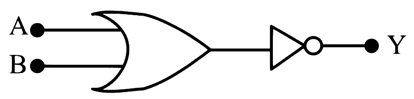
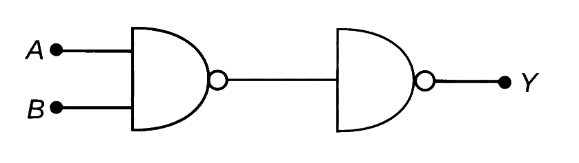
An AND gate is followed by a NOT gate in series. With two input A A A B B B Y Y Y
(a) A + B ‾ \overline{A + B} A + B (b) A ⋅ B ‾ \overline{A \cdot B} A ⋅ B (c) A ⋅ B A \cdot B A ⋅ B (d) A + B A + B A + B Show answer and solution
Answer: (b)
Loading the solution…
Report a mistake Q6 MHT CET 2026 · 16 APR · SHIFT 2 Easy ☆
Logic Gates
In which of the logic gate the following statement is true? "The output is high when either of the inputs is high but not if both inputs are high"
(a) NAND (b) NOR (c) X-OR (d) OR Show answer and solution
Answer: (c)
Loading the solution…
Report a mistake Q7 MHT CET 2026 · 11 APR · SHIFT 2 Easy ☆
Logic Gates
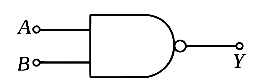
In the case of NAND gate, if A and B are inputs and Y is the output then
(a) Y = A + B ‾ Y = \overline{A + B} Y = A + B (b) Y = A ⋅ B Y = A \cdot B Y = A ⋅ B (c) Y = A ⋅ B ‾ Y = \overline{A \cdot B} Y = A ⋅ B (d) Y = A + B Y = A + B Y = A + B Show answer and solution
Answer: (c)
Loading the solution…
Report a mistake Q8 MHT CET 2026 · 20 APR · SHIFT 2 Easy ☆
Logic Gates
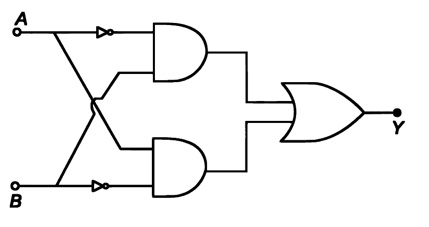
In Boolean expression A + B = Y A + B = Y A + B = Y
(a) Y Y Y A A A B B B A A A B B B (b) Y Y Y A A A B B B (c) Y Y Y A A A B B B (d) Y Y Y A A A B B B A A A B B B Show answer and solution
Answer: (d)
Loading the solution…
Report a mistake Q9 MHT CET 2026 · 20 MAY · SHIFT 1 Medium ☆
Logic Gates
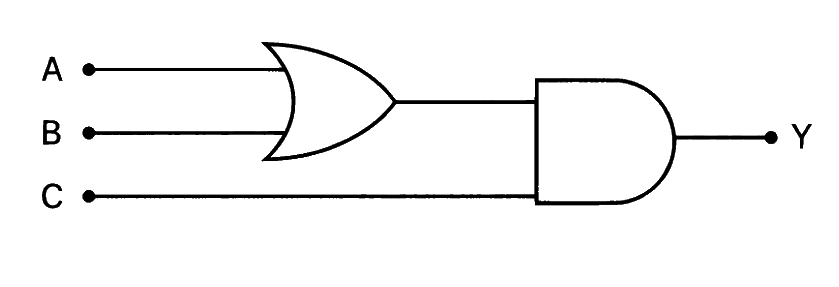
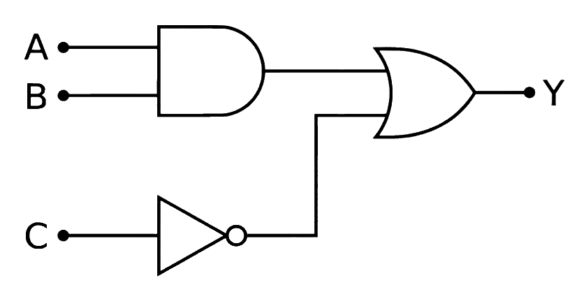
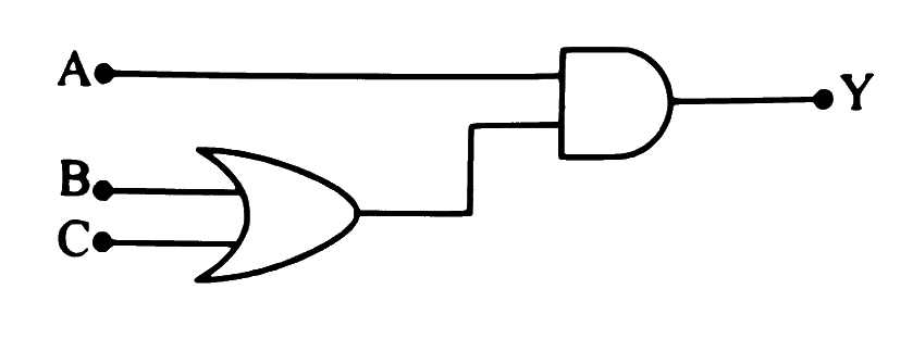
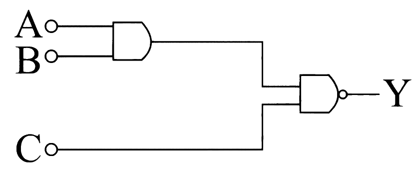
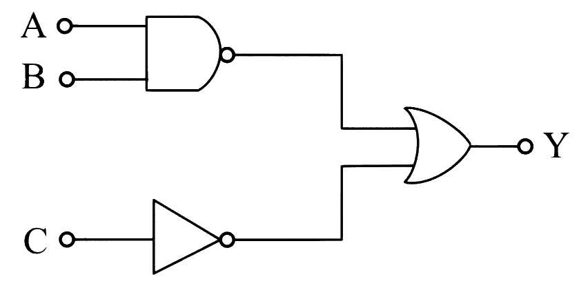
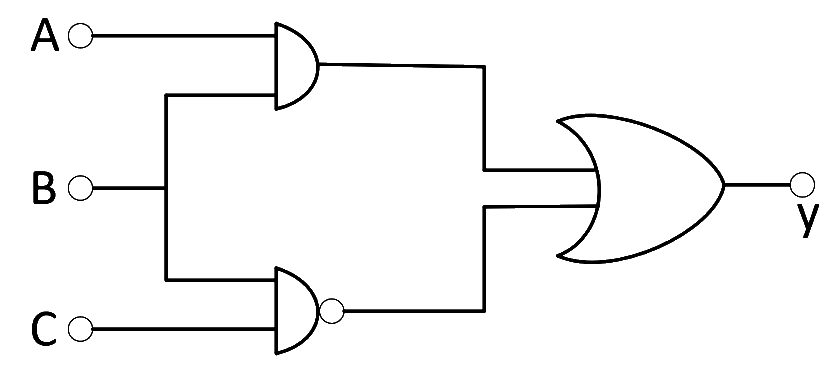
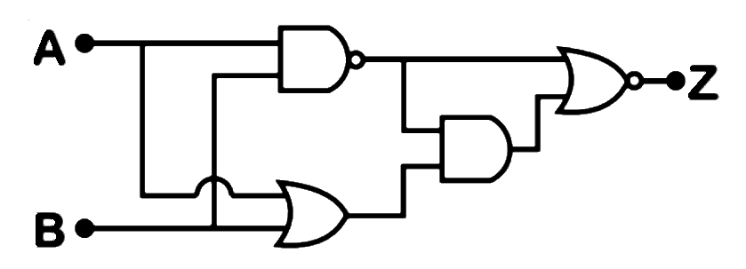
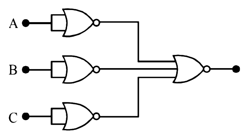
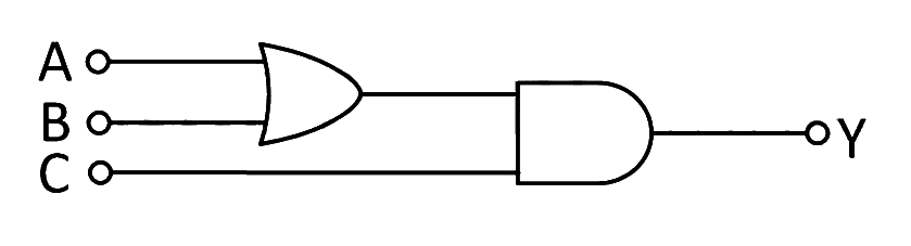
To get output zero for the following circuit, the correct choice for the input is
a. A = 1 , B = 1 , C = 0 A = 1, B = 1, C = 0 A = 1 , B = 1 , C = 0
b. A = 0 , B = 1 , C = 0 A = 0, B = 1, C = 0 A = 0 , B = 1 , C = 0
c. A = 1 , B = 1 , C = 1 A = 1, B = 1, C = 1 A = 1 , B = 1 , C = 1
d. A = 1 , B = 0 , C = 1 A = 1, B = 0, C = 1 A = 1 , B = 0 , C = 1
(a) a and b (b) c and d (c) a and c (d) b and d Show answer and solution
Answer: (a)
Loading the solution…
Report a mistake Q10 MHT CET 2026 · 19 MAY · SHIFT 2 Medium ☆
Logic Gates
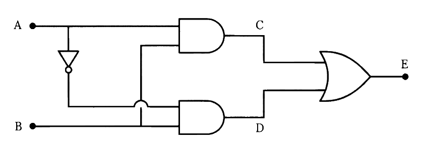
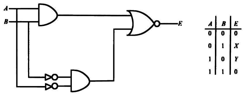
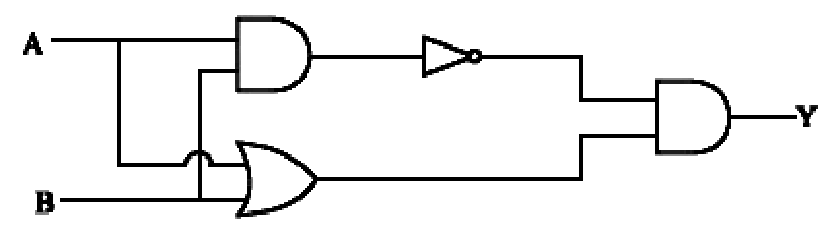
For the logic circuit given below, for
a) input A = 0 A = 0 A = 0 B = 1 B = 1 B = 1
b) input A = 1 A = 1 A = 1 B = 1 B = 1 B = 1 E E E
(a) zero and one. (b) one and zero. (c) zero and zero. (d) one and one. Show answer and solution
Answer: (d)
Loading the solution…
Report a mistake Q11 MHT CET 2026 · 14 MAY · SHIFT 2 Medium ☆
Logic Gates
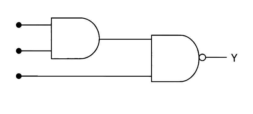
The output Y, when all the three inputs are first high and then low, will respectively be
(a) 1 , 0 1, 0 1 , 0 (b) 1 , 1 1, 1 1 , 1 (c) 0 , 0 0, 0 0 , 0 (d) 0 , 1 0, 1 0 , 1 Show answer and solution
Answer: (d)
Loading the solution…
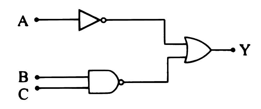
Report a mistake Q12 MHT CET 2026 · 20 APR · SHIFT 1 Medium ☆
Logic Gates
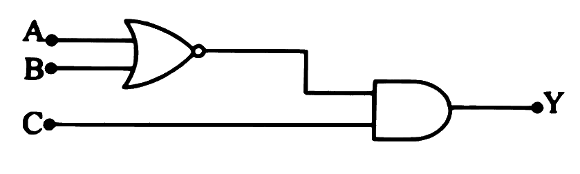
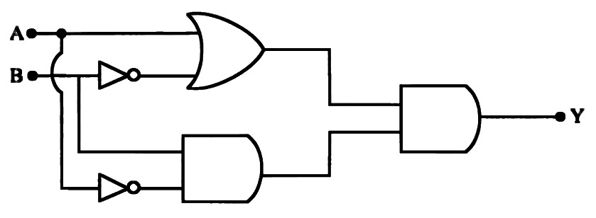
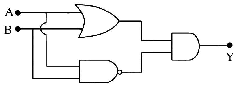
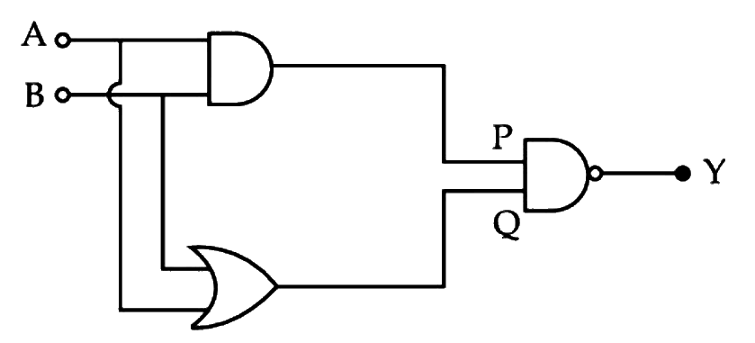
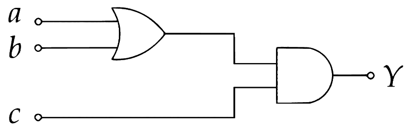
The output Y of the following digital logic circuit will be '1' (one) for the inputs
(a) A = 1 , B = 0 , C = 0 A = 1, B = 0, C = 0 A = 1 , B = 0 , C = 0 (b) A = 1 , B = 0 , C = 1 A = 1, B = 0, C = 1 A = 1 , B = 0 , C = 1 (c) A = 1 , B = 1 , C = 0 A = 1, B = 1, C = 0 A = 1 , B = 1 , C = 0 (d) A = 1 , B = 1 , C = 1 A = 1, B = 1, C = 1 A = 1 , B = 1 , C = 1 Show answer and solution
Answer: (d)
Loading the solution…
Report a mistake Q13 MHT CET 2026 · 19 APR · SHIFT 2 Medium ☆
Logic Gates
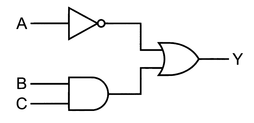
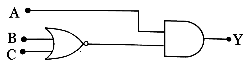
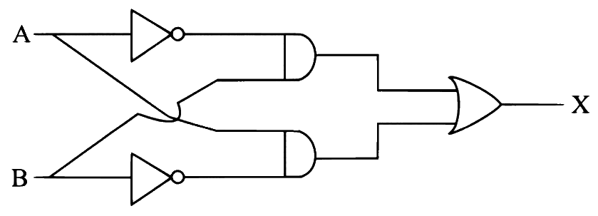
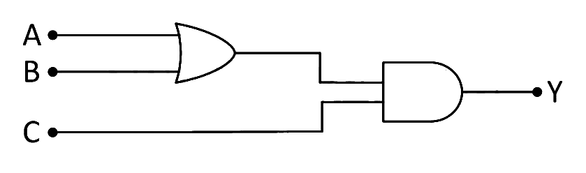
The Boolean expression for the given combination of logic gates is
(a) Y = ( A + B ) ⋅ C ˉ Y = (A + B) \cdot \bar{C} Y = ( A + B ) ⋅ C ˉ (b) Y = ( A ⋅ B ) ⋅ C ˉ Y = (A \cdot B) \cdot \bar{C} Y = ( A ⋅ B ) ⋅ C ˉ (c) Y = ( A + B ) + C Y = (A + B) + C Y = ( A + B ) + C (d) Y = ( A ⋅ B ) + C ˉ Y = (A \cdot B) + \bar{C} Y = ( A ⋅ B ) + C ˉ Show answer and solution
Answer: (d)
Loading the solution…
Report a mistake Q14 MHT CET 2026 · 18 APR · SHIFT 2 Medium ☆
Logic Gates
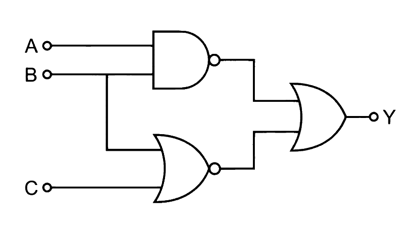
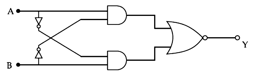
The output Y of the given logic circuit is
(a) ( A ⋅ B ) ‾ + ( C ⋅ B ) ‾ \overline{(A \cdot B)} + \overline{(C \cdot B)} ( A ⋅ B ) + ( C ⋅ B ) (b) ( A + B ) ‾ ⋅ ( B ⋅ C ) ‾ \overline{(A + B)} \cdot \overline{(B \cdot C)} ( A + B ) ⋅ ( B ⋅ C ) (c) ( A ⋅ B ) ‾ + ( B + C ) ‾ \overline{(A \cdot B)} + \overline{(B + C)} ( A ⋅ B ) + ( B + C ) (d) ( A + B ) + ( B + C ) (A + B) + (B + C) ( A + B ) + ( B + C ) Show answer and solution
Answer: (c)
Loading the solution…
Report a mistake Q15 MHT CET 2026 · 17 APR · SHIFT 2 Medium ☆
Logic Gates
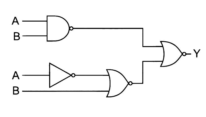
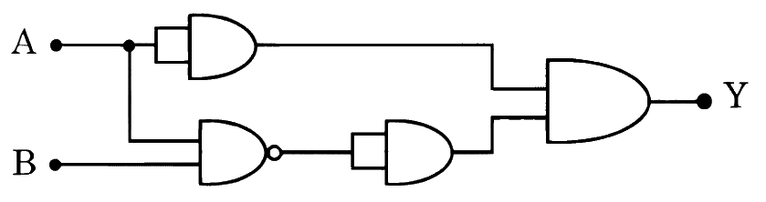
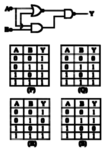
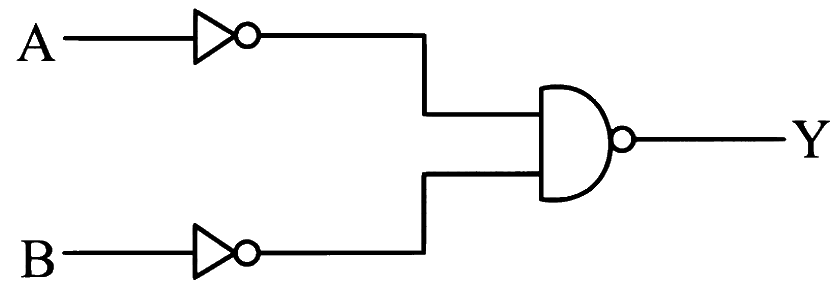
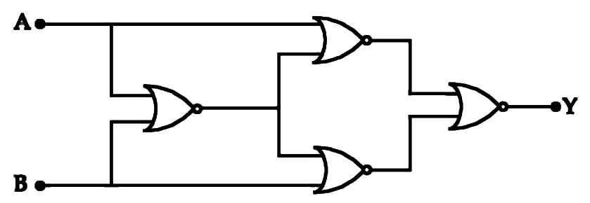
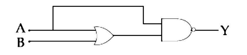
In the following digital circuit, the output 'Y' will be '1' (one) for inputs 'A' and 'B' having values
(a) A = 0 , B = 0 A = 0, B = 0 A = 0 , B = 0 (b) A = 0 , B = 1 A = 0, B = 1 A = 0 , B = 1 (c) A = 1 , B = 0 A = 1, B = 0 A = 1 , B = 0 (d) A = 1 , B = 1 A = 1, B = 1 A = 1 , B = 1 Show answer and solution
Answer: (d)
Loading the solution…
Report a mistake Q16 MHT CET 2026 · 17 APR · SHIFT 1 Medium ☆
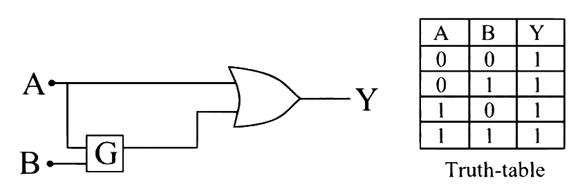
Logic Gates
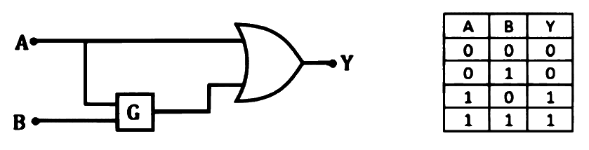
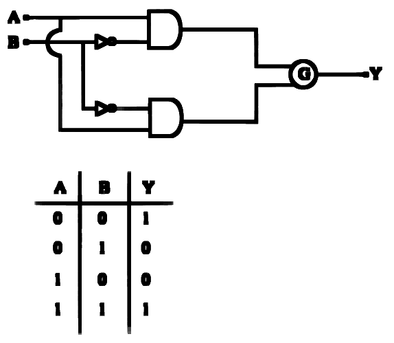
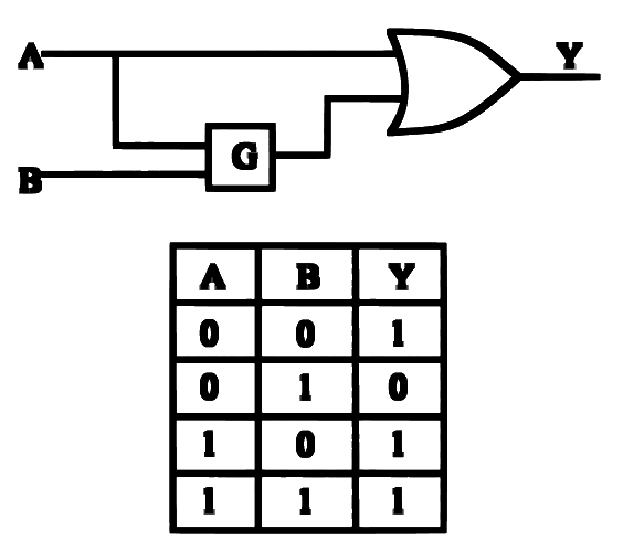
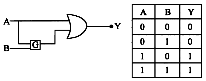
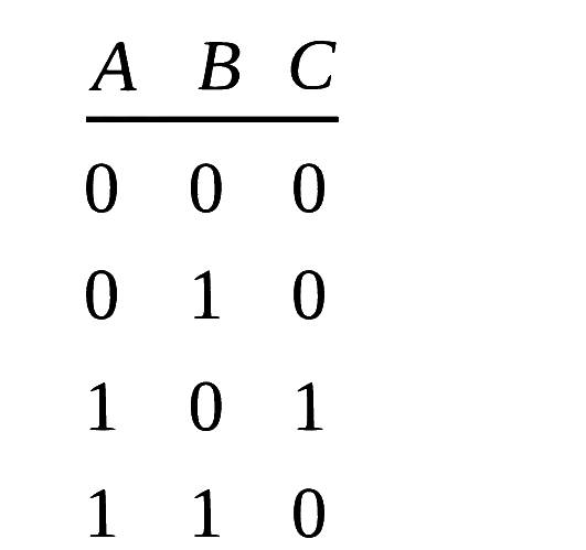
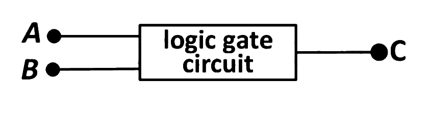
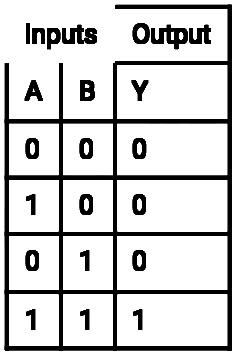
To get the truth table shown from the following logic circuit, the gate G should be
(a) NAND gate. (b) NOR gate. (c) AND gate. (d) OR gate. Show answer and solution
Answer: (c)
Loading the solution…
Report a mistake Q17 JEE Main 2026 · 8 APR · SHIFT 2 Medium ☆
Logic Gates
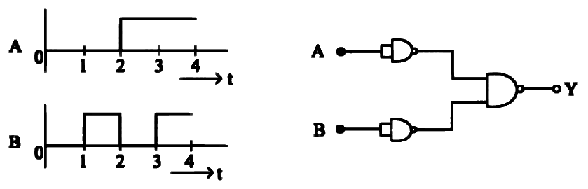
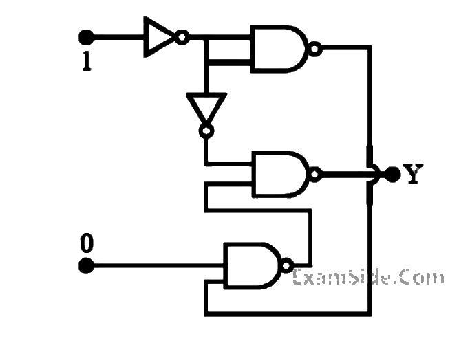
The output Y Y Y A A A B B B
Show answer and solution
Answer: (b)
Loading the solution…
Report a mistake Q18 JEE Main 2026 · 6 APR · SHIFT 2 Medium ☆
Logic Gates
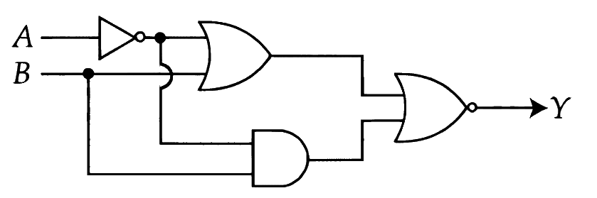
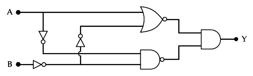
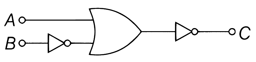
Refer to the logic circuit given below. For two inputs ( A = 1 , B = 1 A = 1, B = 1 A = 1 , B = 1 A = 0 , B = 1 A = 0, B = 1 A = 0 , B = 1 ______ .
(a) 1, 0 respectively (b) 0, 1 respectively (c) 0, 0 respectively (d) 1, 1 respectively Show answer and solution
Answer: (c)
Loading the solution…
Report a mistake Q19 JEE Main 2026 · 5 APR · SHIFT 1 Medium ☆
Logic Gates
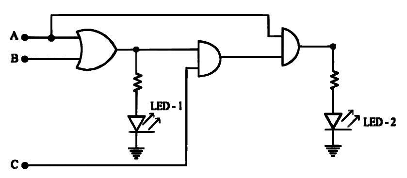
For the given logic circuit, which of the following inputs combination will make both LED-1 and LED- 2 to glow?
(a) A = 0 , B = 1 , C = 1 \mathrm{A} = 0,\ \mathrm{B} = 1, \mathrm{C} = 1 A = 0 , B = 1 , C = 1 (b) A = 1 , B = 0 , C = 0 \mathrm{A} = 1,\ \mathrm{B} = 0, \mathrm{C} = 0 A = 1 , B = 0 , C = 0 (c) A = 1 , B = 0 , C = 1 \mathrm{A} = 1,\ \mathrm{B} = 0, \mathrm{C} = 1 A = 1 , B = 0 , C = 1 (d) A = 1 , B = 1 , C = 0 \mathrm{A} = 1,\ \mathrm{B} = 1, \mathrm{C} = 0 A = 1 , B = 1 , C = 0 Show answer and solution
Answer: (c)
Loading the solution…
Report a mistake Q20 JEE Main 2026 · 23 JAN · SHIFT 2 Medium ☆
Logic Gates
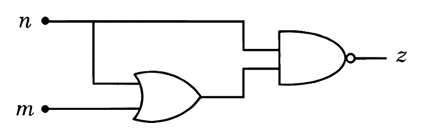
For the given logic gate circuit, which of the following is the correct truth table?
(a) n m z 0 0 1 0 1 1 1 1 0 1 0 0 n \quad m \quad z \quad 0 \quad 0 \quad 1 \quad 0 \quad 1 \quad 1 \quad 1 \quad 1 \quad 0 \quad 1 \quad 0 \quad 0 n m z 0 0 1 0 1 1 1 1 0 1 0 0 (b) n m z 0 0 1 0 1 0 1 1 1 1 0 0 n \quad m \quad z \quad 0 \quad 0 \quad 1 \quad 0 \quad 1 \quad 0 \quad 1 \quad 1 \quad 1 \quad 1 \quad 0 \quad 0 n m z 0 0 1 0 1 0 1 1 1 1 0 0 (c) n m z 0 0 0 0 1 1 1 1 0 1 0 1 n \quad m \quad z \quad 0 \quad 0 \quad 0 \quad 0 \quad 1 \quad 1 \quad 1 \quad 1 \quad 0 \quad 1 \quad 0 \quad 1 n m z 0 0 0 0 1 1 1 1 0 1 0 1 (d) n m z 0 0 1 0 1 0 1 1 0 1 0 0 n \quad m \quad z \quad 0 \quad 0 \quad 1 \quad 0 \quad 1 \quad 0 \quad 1 \quad 1 \quad 0 \quad 1 \quad 0 \quad 0 n m z 0 0 1 0 1 0 1 1 0 1 0 0 Show answer and solution
Answer: (a)
Loading the solution…
Report a mistake Q21 JEE Main 2026 · 22 JAN · SHIFT 2 Medium ☆
Logic Gates
The correct truth table for the given input data of the following logic gate is:
Show answer and solution
Answer: (a)
Loading the solution…
Report a mistake Q22 JEE Main 2026 · 22 JAN · SHIFT 1 Medium ☆
Logic Gates
Find the correct combination of A , B , C \mathrm{A}, \mathrm{B}, \mathrm{C} A , B , C
(a) 1000 (b) 0011 (c) 0100 (d) 1101 Show answer and solution
Answer: (d)
Loading the solution…
Report a mistake Q23 MHT CET 2026 · 13 MAY · SHIFT 2 Medium ☆
Logic Gates
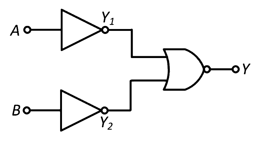
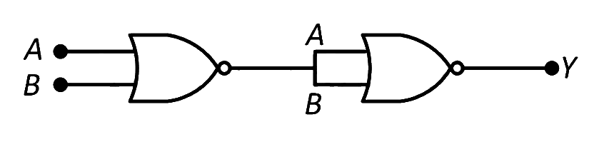
The following circuit is equivalent to
(a) AND gate (b) NAND gate (c) NOR gate (d) OR gate Show answer and solution
Answer: (c)
Loading the solution…
Report a mistake Q24 MHT CET 2026 · 12 MAY · SHIFT 2 Medium ☆
Logic Gates
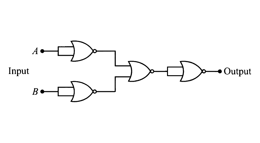
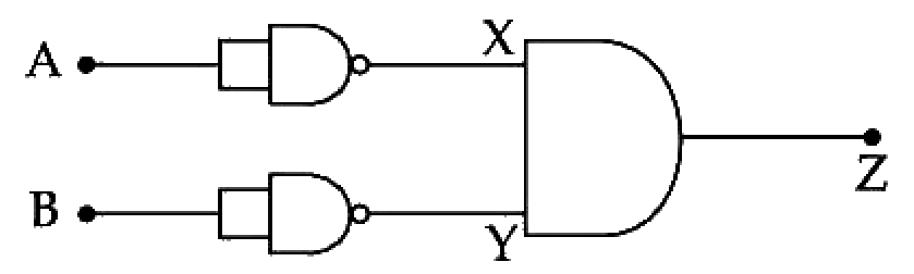
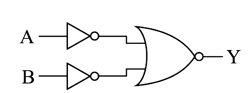
The output Y Y Y
(a) AND gate (b) NAND gate (c) OR gate (d) NOR gate Show answer and solution
Answer: (d)
Loading the solution…
Report a mistake Q25 MHT CET 2026 · 12 MAY · SHIFT 1 Medium ☆
Logic Gates
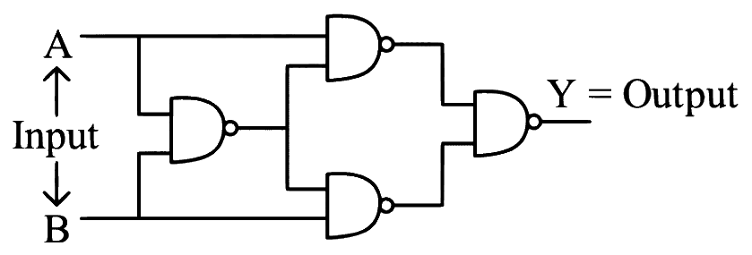
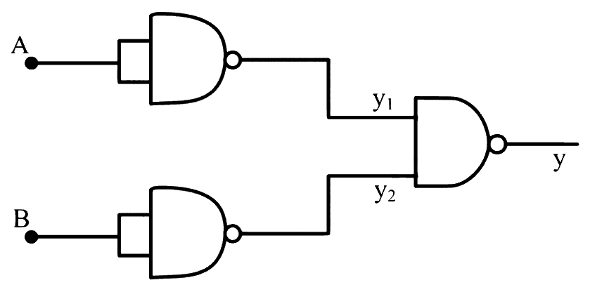
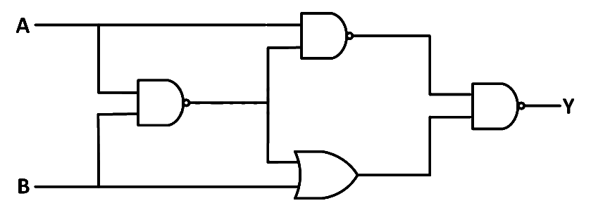
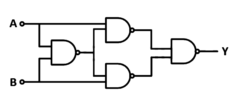
The truth table for the system of four NAND gates as shown in the figure is
(a) (b) (c) (d) 0 1 0 1 0 1 1 1 1 \begin{array}{|c|c|c|}\hline 0 & 1 & 0 \\ \hline\end{array} \quad \begin{array}{|c|c|c|}\hline 1 & 0 & 1 \\ \hline\end{array} \quad \begin{array}{|c|c|c|}\hline 1 & 1 & 1 \\ \hline\end{array} 0 1 0 1 0 1 1 1 1 Show answer and solution
Answer: (c)
Loading the solution…
Report a mistake Q26 MHT CET 2026 · 16 APR · SHIFT 1 Medium ☆
Logic Gates
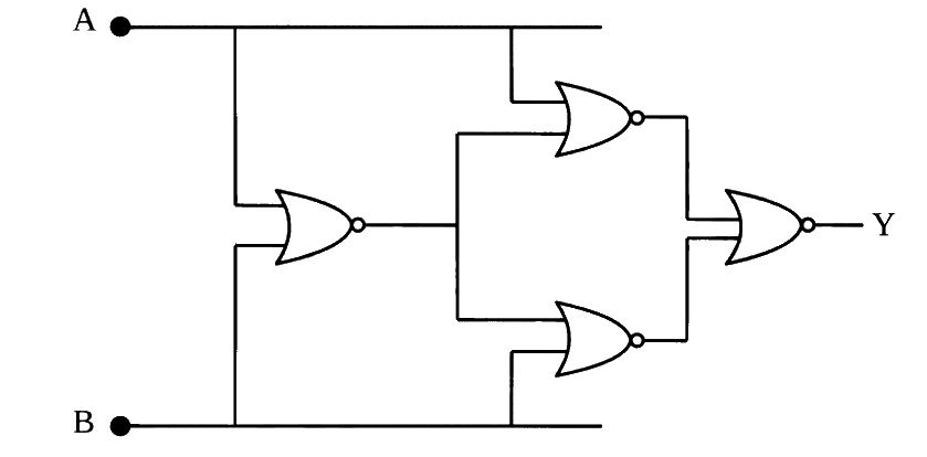
The resultant gate and its Boolean expression in the given circuit is
______
(a) AND, , , + + + (b) NAND, , , + + + (c) OR, , , + + + (d) NOR, , , − - − Show answer and solution
Answer: (c)
Loading the solution…
Report a mistake Q27 MHT CET 2026 · 11 APR · SHIFT 1 Medium ☆
Logic Gates
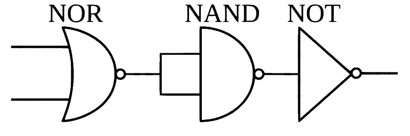
What does the following combination of gates produce?
(a) NAND gate (b) NOR gate (c) XOR gate (d) AND gate Show answer and solution
Answer: (a)
Loading the solution…
Report a mistake Q28 JEE Main 2026 · 2 APR · SHIFT 2 Medium ☆
Logic Gates
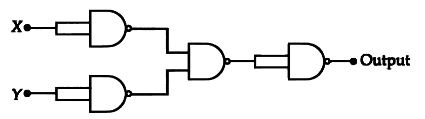
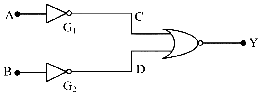
If X and Y are the inputs, the given circuit works as _________.
(a) OR gate (b) AND gate (c) NAND gate (d) NOR gate Show answer and solution
Answer: (d)
Loading the solution…
Report a mistake Q29 JEE Main 2026 · 28 JAN · SHIFT 2 Medium ☆
Logic Gates
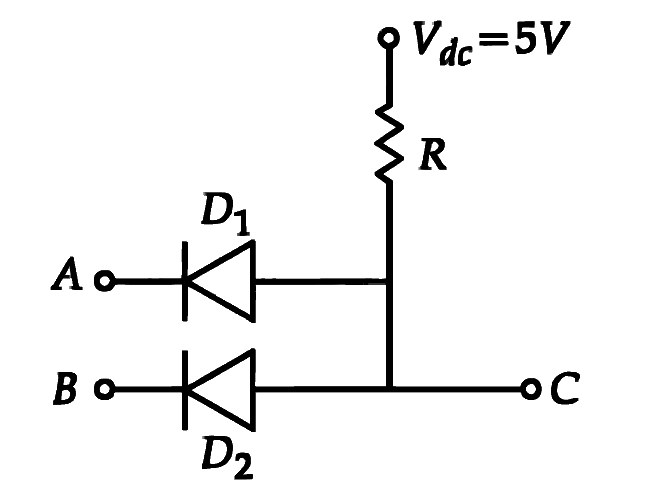
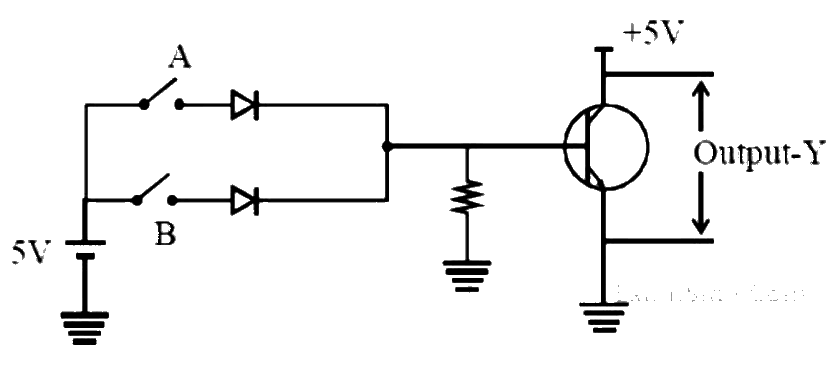
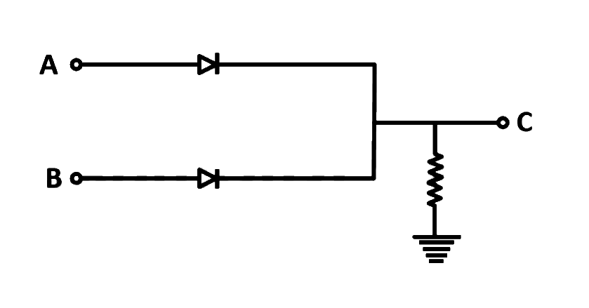
Two p-n junction diodes D 1 D_1 D 1 D 2 D_2 D 2 A A A B B B C C C
(a) AND Gate (b) OR Gate (c) NOR Gate (d) NAND Gate Show answer and solution
Answer: (a)
Loading the solution…
Report a mistake Q30 JEE Main 2026 · 24 JAN · SHIFT 2 Medium ☆
Logic Gates
Identify the correct truth table of the given logic circuit.
(a) A B Y 0 0 0 0 1 0 1 0 1 1 1 0 0 \quad 0 \quad 0 \quad 0 \quad 1 \quad 0 \quad 1 \quad 0 \quad 1 \quad 1 \quad 1 \quad 0 0 0 0 0 1 0 1 0 1 1 1 0 (b) A B Y 0 0 0 0 1 1 1 0 1 1 1 0 0 \quad 0 \quad 0 \quad 0 \quad 1 \quad 1 \quad 1 \quad 0 \quad 1 \quad 1 \quad 1 \quad 0 0 0 0 0 1 1 1 0 1 1 1 0 (c) A B Y 0 0 1 0 1 1 1 0 1 1 1 0 0 \quad 0 \quad 1 \quad 0 \quad 1 \quad 1 \quad 1 \quad 0 \quad 1 \quad 1 \quad 1 \quad 0 0 0 1 0 1 1 1 0 1 1 1 0 (d) A B Y 0 0 1 0 1 0 1 0 1 1 1 0 0 \quad 0 \quad 1 \quad 0 \quad 1 \quad 0 \quad 1 \quad 0 \quad 1 \quad 1 \quad 1 \quad 0 0 0 1 0 1 0 1 0 1 1 1 0 Show answer and solution
Answer: (a)
Loading the solution…
Report a mistake Q31 JEE Main 2026 · 21 JAN · SHIFT 1 Medium ☆
Logic Gates
The given circuit works as:
(a) NOR gate (b) OR gate (c) AND gate (d) NAND gate Show answer and solution
Answer: (d)
Loading the solution…
Report a mistake Q32 MHT CET 2026 · 15 APR · SHIFT 2 Difficult ☆
Logic Gates
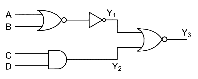
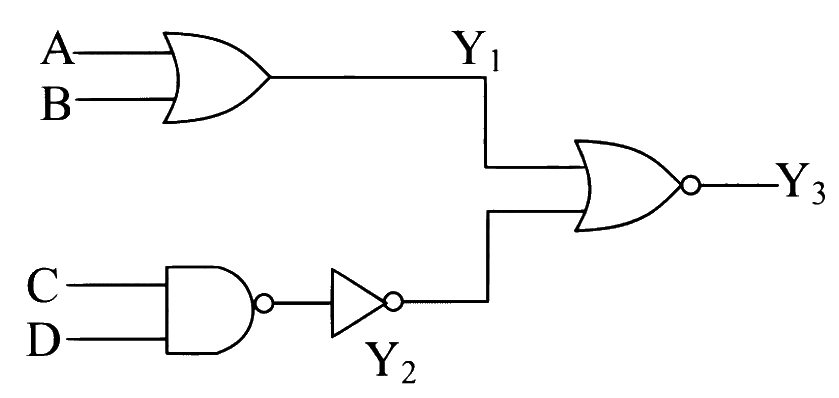
In the logic circuit diagram, when all the four inputs, A, B, C, D are 'one' the outputs Y 1 , Y 2 , Y 3 Y_1, Y_2, Y_3 Y 1 , Y 2 , Y 3 Y 1 , Y 2 , Y 3 Y_1, Y_2, Y_3 Y 1 , Y 2 , Y 3
(a) 1 , 1 , 1 1, 1, 1 1 , 1 , 1 (b) 1 , 0 , 0 1, 0, 0 1 , 0 , 0 (c) 0 , 1 , 0 0, 1, 0 0 , 1 , 0 (d) 0 , 0 , 1 0, 0, 1 0 , 0 , 1 Show answer and solution
Answer: (b)
Loading the solution…
Report a mistake Q33 JEE Main 2026 · 4 APR · SHIFT 1 Difficult ☆
Logic Gates
Two 4 bits binary numbers, A = 1101 A = 1101 A = 1101 B = 1010 B = 1010 B = 1010 ( Y ) (Y) ( Y )
(a) Y = 1101 Y = 1101 Y = 1101 (b) Y = 0010 Y = 0010 Y = 0010 (c) Y = 0111 Y = 0111 Y = 0111 (d) Y = 1000 Y = 1000 Y = 1000 Show answer and solution
Answer: (a)
Loading the solution…
Report a mistake Q34 MHT CET 2025 · 26 APR · SHIFT 2 Easy ☆
Logic Gates
In a certain 2 -inputs logic gate, when inputs A = 0 \mathrm{A} = 0 A = 0 B = 0 \mathrm{B} = 0 B = 0 C = 1 \mathrm{C} = 1 C = 1 A = 0 , B = 1 \mathrm{A} = 0,\ \mathrm{B} = 1 A = 0 , B = 1 C = 1 \mathrm{C} = 1 C = 1
Show answer and solution
Answer: (c)
Loading the solution…
Report a mistake Q35 MHT CET 2025 · 5 MAY · SHIFT 2 Easy ☆
Logic Gates
An AND gate is followed by a NOT gate in series. With two inputs ' A A A B B B
(a) A + B ‾ \overline{\mathrm{A} + \mathrm{B}} A + B (b) A ⋅ B ‾ \overline{\mathrm{A} \cdot \mathrm{B}} A ⋅ B (c) A ⋅ B \mathrm{A} \cdot \mathrm{B} A ⋅ B (d) A + B \mathrm{A} + \mathrm{B} A + B Show answer and solution
Answer: (b)
Loading the solution…
Report a mistake Q36 MHT CET 2025 · 25 APR · SHIFT 1 Easy ☆
Logic Gates
The logic gate for which the output goes 'HIGH' or ' 1 ' only when an odd number of 'HIGH' or ' 1 ' are at its input, is
(a) OR gate (b) NAND gate (c) Ex-OR gate (d) NOR gate Show answer and solution
Answer: (c)
Loading the solution…
Report a mistake Q37 MHT CET 2025 · 21 APR · SHIFT 1 Easy ☆
Logic Gates
Which of the following logic gates is called as Universal gate?
(a) OR (b) X-OR (c) AND (d) NAND Show answer and solution
Answer: (d)
Loading the solution…
Report a mistake Q38 MHT CET 2025 · 25 APR · SHIFT 2 Medium ☆
Logic Gates
One of the following values of inputs A , B \mathrm{A}, \mathrm{B} A , B ( Y ) (\mathrm{Y}) ( Y )
(a) 0 , 0 , 0 0, 0, 0 0 , 0 , 0 (b) 0 , 1 , 0 0, 1, 0 0 , 1 , 0 (c) 1 , 0 , 0 1, 0, 0 1 , 0 , 0 (d) 1 , 0 , 1 1, 0, 1 1 , 0 , 1 Show answer and solution
Answer: (d)
Loading the solution…
Report a mistake Q39 MHT CET 2025 · 25 APR · SHIFT 1 Medium ☆
Logic Gates
To get output of the following logic circuit as ' 0 ' (zero), the inputs A , B , C A, B, C A , B , C
(a) 1 , 1 , 0 1, 1, 0 1 , 1 , 0 (b) 0 , 1 , 0 0, 1, 0 0 , 1 , 0 (c) 1 , 0 , 1 1, 0, 1 1 , 0 , 1 (d) 0 , 0 , 1 0, 0, 1 0 , 0 , 1 Show answer and solution
Answer: (d)
Loading the solution…
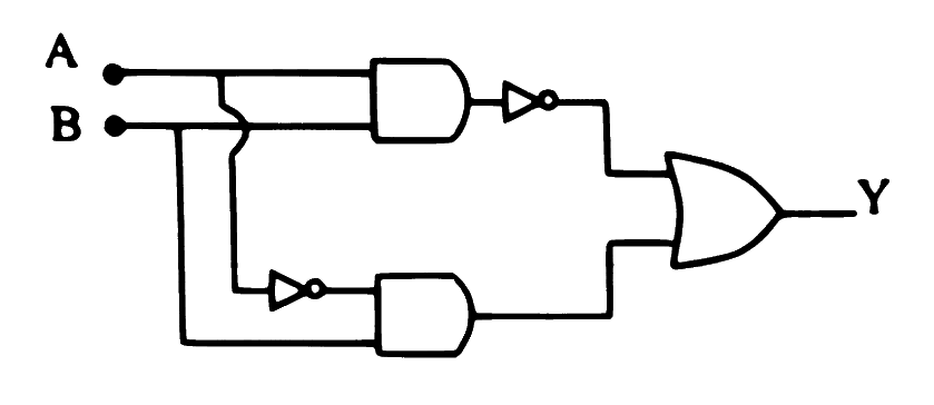
Report a mistake Q40 MHT CET 2025 · 22 APR · SHIFT 2 Medium ☆
Logic Gates
In the logic circuit given, A , B \mathrm{A}, \mathrm{B} A , B
(a) for all the HIGH inputs. (b) for all the LOW inputs. (c) when A = 1 , B = 0 , C = 0 \mathrm{A} = 1,\ \mathrm{B} = 0,\ \mathrm{C} = 0 A = 1 , B = 0 , C = 0 (d) when A = 1 , B = 0 , C = 1 \mathrm{A} = 1,\ \mathrm{B} = 0,\ \mathrm{C} = 1 A = 1 , B = 0 , C = 1 Show answer and solution
Answer: (c)
Loading the solution…
Report a mistake Q41 MHT CET 2025 · 21 APR · SHIFT 2 Medium ☆
Logic Gates
In the following combination of logic gates, the output Y Y Y A A A
(a) ( A ⋅ B ‾ ) + ( A ‾ ⋅ B ) (\mathrm{A} \cdot \overline{\mathrm{B}}) + (\overline{\mathrm{A}} \cdot \mathrm{B}) ( A ⋅ B ) + ( A ⋅ B ) (b) ( A ⋅ B ) + ( A ‾ ⋅ B ) (\mathrm{A} \cdot \mathrm{B}) + (\overline{\mathrm{A}} \cdot \mathrm{B}) ( A ⋅ B ) + ( A ⋅ B ) (c) ( A ⋅ B ‾ ) + ( A ‾ ⋅ B ) (\overline{\mathrm{A} \cdot \mathrm{B}}) + (\overline{\mathrm{A}} \cdot \mathrm{B}) ( A ⋅ B ) + ( A ⋅ B ) (d) ( A ⋅ B ‾ ) + ( A ⋅ B ‾ ) (\overline{\mathrm{A} \cdot \mathrm{B}}) + (\mathrm{A} \cdot \overline{\mathrm{B}}) ( A ⋅ B ) + ( A ⋅ B ) Show answer and solution
Answer: (c)
Loading the solution…
Report a mistake Q42 MHT CET 2025 · 19 APR · SHIFT 2 Medium ☆
Logic Gates
In a given logic circuit, the output Y when all the three inputs A , B , C \mathrm{A}, \mathrm{B}, \mathrm{C} A , B , C
(a) ( 0 , 0 ) (0, 0) ( 0 , 0 ) (b) ( 0 , 1 ) (0, 1) ( 0 , 1 ) (c) ( 1 , 0 ) (1, 0) ( 1 , 0 ) (d) ( 1 , 1 ) (1, 1) ( 1 , 1 ) Show answer and solution
Answer: (c)
Loading the solution…
Report a mistake Q43 JEE Main 2025 · 7 APR · SHIFT 2 Medium ☆
Logic Gates
Consider the following logic circuit.
The output is Y = 0 when:
(a) A = 1 and B = 0 (b) A = 0 and B = 0 (c) A = 1 and B = 1 (d) A = 0 and B = 1 Show answer and solution
Answer: (c)
Loading the solution…
Report a mistake Q44 JEE Main 2025 · 3 APR · SHIFT 2 Medium ☆
Logic Gates
The truth table corresponding to the circuit given below is:
(a) A B C 0 0 0 0 1 0 1 0 1 1 1 1 \mathrm{A} \quad \mathrm{B} \quad \mathrm{C} \quad 0 \quad 0 \quad 0 \quad 0 \quad 1 \quad 0 \quad 1 \quad 0 \quad 1 \quad 1 \quad 1 \quad 1 A B C 0 0 0 0 1 0 1 0 1 1 1 1 (b) A B C 0 0 1 1 0 0 0 1 0 1 1 0 \mathrm{B} \quad \mathrm{C} \quad 0 \quad 0 \quad 1 \quad 1 \quad 0 \quad 0 \quad 0 \quad 1 \quad 0 \quad 1 \quad 1 \quad 0 B C 0 0 1 1 0 0 0 1 0 1 1 0 (c) A B C 0 0 1 0 1 0 1 0 0 1 1 0 \mathrm{B} \quad \mathrm{C} \quad 0 \quad 0 \quad 1 \quad 0 \quad 1 \quad 0 \quad 1 \quad 0 \quad 0 \quad 1 \quad 1 \quad 0 B C 0 0 1 0 1 0 1 0 0 1 1 0 (d) A B C 0 0 0 1 0 0 0 1 0 1 1 1 \mathrm{A} \quad \mathrm{B} \quad \mathrm{C} \quad 0 \quad 0 \quad 0 \quad 1 \quad 0 \quad 0 \quad 0 \quad 1 \quad 0 \quad 1 \quad 1 \quad 1 A B C 0 0 0 1 0 0 0 1 0 1 1 1 Show answer and solution
Answer: (a)
Loading the solution…
Report a mistake Q45 JEE Main 2025 · 3 APR · SHIFT 1 Medium ☆
Logic Gates
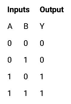
Choose the correct logic circuit for the given truth table having inputs A and B.
Show answer and solution
Answer: (a)
Loading the solution…
Report a mistake Q46 JEE Main 2025 · 2 APR · SHIFT 2 Medium ☆
Logic Gates
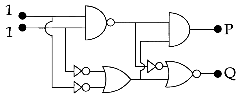
In the digital circuit shown in the figure, for the given inputs the P P P Q Q Q
(a) P = 0 , Q = 1 P = 0, Q = 1 P = 0 , Q = 1 (b) P = 1 , Q = 0 P = 1, Q = 0 P = 1 , Q = 0 (c) P = 0 , Q = 0 \mathrm{P} = 0, \mathrm{Q} = 0 P = 0 , Q = 0 (d) P = 1 , Q = 1 P = 1, Q = 1 P = 1 , Q = 1 Show answer and solution
Answer: (c)
Loading the solution…
Report a mistake Q47 JEE Main 2025 · 29 JAN · SHIFT 2 Medium ☆
Logic Gates
The truth table for the circuit given below is:
Show answer and solution
Answer: (d)
Loading the solution…
Report a mistake Q48 JEE Main 2025 · 28 JAN · SHIFT 1 Medium ☆
Logic Gates
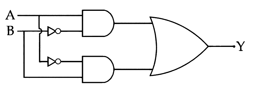
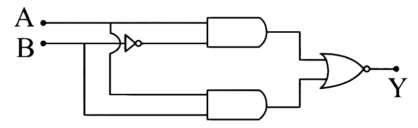
Which of the following circuits has the same output as that of the given circuit?
Show answer and solution
Answer: (a)
Loading the solution…
Report a mistake Q49 JEE Main 2025 · 22 JAN · SHIFT 2 Medium ☆
Logic Gates
To obtain the given truth table, following logic gate should be placed at G:
(a) NOR Gate (b) OR Gate (c) AND Gate (d) NAND Gate Show answer and solution
Answer: (a)
Loading the solution…
Report a mistake Q50 MHT CET 2025 · 20 APR · SHIFT 2 Medium ☆
Logic Gates
The resultant logic gate from the combination of following gates is
Show answer and solution
Answer: (a)
Loading the solution…
Report a mistake Q51 NEET 2025 Medium ☆
Logic Gates
The output ( Y Y Y
Show answer and solution
Answer: (b)
Loading the solution…
Report a mistake Q52 JEE Main 2025 · 29 JAN · SHIFT 1 Medium ☆
Logic Gates
For the circuit shown above, equivalent GATE is:
(a) NOT gate (b) NAND gate (c) AND gate (d) OR gate Show answer and solution
Answer: (d)
Loading the solution…
Report a mistake Q53 JEE Main 2025 · 4 APR · SHIFT 1 Difficult ☆
Logic Gates
The Boolean expression Y = A B ˉ C + A ˉ C ˉ \mathrm{Y} = A\bar{B}C + \bar{A}\bar{C} Y = A B ˉ C + A ˉ C ˉ
A. One 3-input AND gate, 3 NOT gates and one 2-input OR gate, one 2-input AND gate B. One 3 -input AND gate, 1 NOT gate, One 2 -input NOR gate and one 2 -input OR gate C. 3 -input OR gate, 3 NOT gates and one 2 -input AND gate
Choose the correct answer from the options given below:
(a) B, C Only (b) A, B, C Only (c) A, B Only (d) A, C Only Show answer and solution
Answer: (c)
Loading the solution…
Report a mistake Q54 JEE Main 2025 · 24 JAN · SHIFT 2 Difficult ☆
Logic Gates
The output of the circuit is low (zero) for:
(A) X = 0 , Y = 0 X = 0, Y = 0 X = 0 , Y = 0
(B) X = 0 , Y = 1 X = 0, Y = 1 X = 0 , Y = 1
(C) X = 1 , Y = 0 X = 1, Y = 0 X = 1 , Y = 0
(D) X = 1 , Y = 1 X = 1, Y = 1 X = 1 , Y = 1
Choose the correct answer from the options given below:
(a) (A), (B) and (C) only (b) (A), (C) and (D) only (c) (B), (C) and (D) only (d) (A), (B) and (D) only Show answer and solution
Answer: (c)
Loading the solution…
Report a mistake Q55 MHT CET 2024 · 15 MAY · SHIFT 1 Easy ☆
Logic Gates
Two different logic gates giving output ' 1 ' for the inputs ( 1 , 0 ) (1, 0) ( 1 , 0 ) ( 0 , 1 ) (0, 1) ( 0 , 1 )
(a) 'AND', 'OR' (b) 'OR', 'NOR' (c) 'NAND', 'NOR' (d) 'NAND', 'OR' Show answer and solution
Answer: (d)
Loading the solution…
Report a mistake Q56 MHT CET 2024 · 3 MAY · SHIFT 2 Easy ☆
Logic Gates
The Boolean expression for 'X-OR' gate C = ( A ⊕ B ) C = (A \oplus B) C = ( A ⊕ B )
(a) ( A ⋅ B ) + ( A ‾ ⋅ B ‾ ) (\mathrm{A} \cdot \mathrm{B}) + (\overline{\mathrm{A}} \cdot \overline{\mathrm{B}}) ( A ⋅ B ) + ( A ⋅ B ) (b) A + ( A ‾ ⋅ B ‾ ) \mathrm{A} + (\overline{\mathrm{A}} \cdot \overline{\mathrm{B}}) A + ( A ⋅ B ) (c) ( A ⋅ B ) + B ‾ (\mathrm{A} \cdot \mathrm{B}) + \overline{\mathrm{B}} ( A ⋅ B ) + B (d) ( A ‾ ⋅ B ) + ( A ⋅ B ‾ ) (\overline{\mathrm{A}} \cdot \mathrm{B}) + (\mathrm{A} \cdot \overline{\mathrm{B}}) ( A ⋅ B ) + ( A ⋅ B ) Show answer and solution
Answer: (d)
Loading the solution…
Report a mistake Q57 NEET 2024 Easy ☆
Logic Gates
When the output of an OR gate is applied as input to a NOT gate, then the combination acts as a
(a) NAND gate (b) NOR gate (c) AND gate (d) OR gate Show answer and solution
Answer: (b)
Loading the solution…
Report a mistake Q58 MHT CET 2024 · 3 MAY · SHIFT 2 Medium ☆
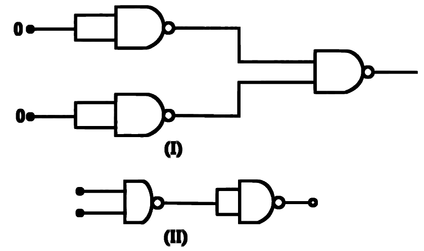
Logic Gates
The combination of NAND gates is shown in figure (I) and (II). For the given inputs, the outputs in both the combinations are respectively.
(a) 0, 0 (b) 0, 1 (c) 1, 0 (d) 1, 1 Show answer and solution
Answer: (b)
Loading the solution…
Report a mistake Q59 MHT CET 2024 · 16 MAY · SHIFT 2 Medium ☆
Logic Gates
To get the truth table shown from the following logic circuit, the logic gate G should be
Show answer and solution
Answer: (c)
Loading the solution…
Report a mistake Q60 MHT CET 2024 · 16 MAY · SHIFT 2 Medium ☆
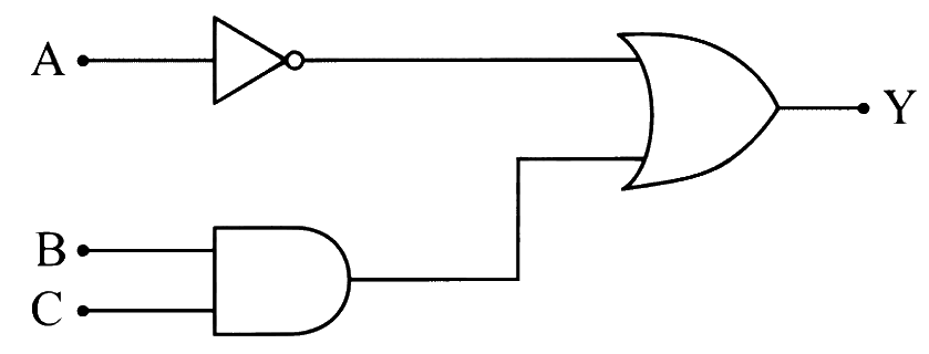
Logic Gates
The Boolean expression for the given combination of logic gates is
(a) Y = ( A ‾ ⋅ B ) + C \mathrm{Y} = (\overline{\mathrm{A}} \cdot \mathrm{B}) + \mathrm{C} Y = ( A ⋅ B ) + C (b) Y = ( A ‾ + B ) ⋅ C \mathrm{Y} = (\overline{\mathrm{A}} + \mathrm{B}) \cdot \mathrm{C} Y = ( A + B ) ⋅ C (c) Y = A ‾ + ( B ⋅ C ) \mathrm{Y} = \overline{\mathrm{A}} + (\mathrm{B} \cdot \mathrm{C}) Y = A + ( B ⋅ C ) (d) Y = A ‾ ⋅ ( B + C ) \mathrm{Y} = \overline{\mathrm{A}} \cdot (\mathrm{B} + \mathrm{C}) Y = A ⋅ ( B + C ) Show answer and solution
Answer: (c)
Loading the solution…
Report a mistake Q61 MHT CET 2024 · 16 MAY · SHIFT 1 Medium ☆
Logic Gates
The truth table of the following circuit is
Show answer and solution
Answer: (c)
Loading the solution…
Report a mistake Q62 MHT CET 2024 · 11 MAY · SHIFT 2 Medium ☆
Logic Gates
For the following digital logic circuit, the correct truth-table is
Show answer and solution
Answer: (d)
Loading the solution…
Report a mistake Q63 MHT CET 2024 · 10 MAY · SHIFT 1 Medium ☆
Logic Gates
What is the output Y in the following circuit, when all the three inputs A, B, C are first 'zero' and then 'one'?
(a) 0, 0 (b) 0, 1 (c) 1, 0 (d) 1, 1 Show answer and solution
Answer: (c)
Loading the solution…
Report a mistake Q64 MHT CET 2024 · 9 MAY · SHIFT 1 Medium ☆
Logic Gates
In the logic circuit diagram, when all the four inputs A , B , C , D \mathrm{A}, \mathrm{B}, \mathrm{C}, \mathrm{D} A , B , C , D Y 1 , Y 2 , Y 3 \mathrm{Y}_1, \mathrm{Y}_2, \mathrm{Y}_3 Y 1 , Y 2 , Y 3 ( 1 , 1 , 0 ) (1, 1, 0) ( 1 , 1 , 0 ) A , B , C , D \mathrm{A}, \mathrm{B}, \mathrm{C}, \mathrm{D} A , B , C , D Y 1 , Y 2 , Y 3 \mathrm{Y}_1, \mathrm{Y}_2, \mathrm{Y}_3 Y 1 , Y 2 , Y 3
(a) ( 0 , 1 , 0 ) (0, 1, 0) ( 0 , 1 , 0 ) (b) ( 0 , 0 , 1 ) (0, 0, 1) ( 0 , 0 , 1 ) (c) ( 1 , 1 , 0 ) (1, 1, 0) ( 1 , 1 , 0 ) (d) ( 1 , 1 , 1 ) (1, 1, 1) ( 1 , 1 , 1 ) Show answer and solution
Answer: (b)
Loading the solution…
Report a mistake Q65 MHT CET 2024 · 4 MAY · SHIFT 2 Medium ☆
Logic Gates
The truth table for the given logic circuit is
Show answer and solution
Answer: (a)
Loading the solution…
Report a mistake Q66 NEET 2024 Medium ☆
Logic Gates
The output Y for the inputs A and B of the given logic circuit is:
(a) A ⋅ B A \cdot B A ⋅ B (b) A ˉ ⋅ B ˉ \bar{A} \cdot \bar{B} A ˉ ⋅ B ˉ (c) A + B A + B A + B (d) A ˉ + B ˉ \bar{A} + \bar{B} A ˉ + B ˉ Show answer and solution
Answer: (c)
Loading the solution…
Report a mistake Q67 NEET 2024 Medium ☆
Logic Gates
A logic circuit provides the output Y Y Y
The expression of the output Y is:
(a) A ⋅ B + A ˉ A \cdot B + \bar{A} A ⋅ B + A ˉ (b) A ⋅ B ˉ + A ˉ A \cdot \bar{B} + \bar{A} A ⋅ B ˉ + A ˉ (c) B ˉ \bar{B} B ˉ (d) B Show answer and solution
Answer: (c)
Loading the solution…
Report a mistake Q68 JEE Main 2024 · 9 APR · SHIFT 2 Medium ☆
Logic Gates
In the truth table of the above circuit the value of X and Y are:
(a) 1, 1 (b) 0, 1 (c) 1, 0 (d) 0, 0 Show answer and solution
Answer: (a)
Loading the solution…
Report a mistake Q69 JEE Main 2024 · 8 APR · SHIFT 1 Medium ☆
Logic Gates
The output Y \mathrm{Y} Y
(a) A ⋅ B A \cdot B A ⋅ B (b) A ˉ ⋅ B \bar{A} \cdot B A ˉ ⋅ B (c) A ⋅ B ( A + B ) A \cdot B(A + B) A ⋅ B ( A + B ) (d) 0 Show answer and solution
Answer: (d)
Loading the solution…
Report a mistake Q70 JEE Main 2024 · 6 APR · SHIFT 1 Medium ☆
Logic Gates
The correct truth table for the following logic circuit is:
Show answer and solution
Answer: (b)
Loading the solution…
Report a mistake Q71 JEE Main 2024 · 5 APR · SHIFT 2 Medium ☆
Logic Gates
The output (Y) of logic circuit given below is 0 only when:
(a) A = 0 , B = 0 \mathrm{A} = 0,\ \mathrm{B} = 0 A = 0 , B = 0 (b) A = 0 , B = 1 \mathrm{A} = 0,\ \mathrm{B} = 1 A = 0 , B = 1 (c) A = 1 , B = 0 \mathrm{A} = 1,\ \mathrm{B} = 0 A = 1 , B = 0 (d) A = 1 , B = 1 \mathrm{A} = 1, \mathrm{B} = 1 A = 1 , B = 1 Show answer and solution
Answer: (a)
Loading the solution…
Report a mistake Q72 JEE Main 2024 · 5 APR · SHIFT 1 Medium ☆
Logic Gates
Following gates section is connected in a complete suitable circuit.
For which of the following combination, bulb will glow (ON):
(a) A = 1 , B = 1 , C = 1 , D = 0 \mathrm{A} = 1,\ \mathrm{B} = 1, \mathrm{C} = 1, \mathrm{D} = 0 A = 1 , B = 1 , C = 1 , D = 0 (b) A = 1 , B = 0 , C = 0 , D = 0 \mathrm{A} = 1,\ \mathrm{B} = 0, \mathrm{C} = 0, \mathrm{D} = 0 A = 1 , B = 0 , C = 0 , D = 0 (c) A = 0 , B = 0 , C = 0 , D = 1 \mathrm{A} = 0,\ \mathrm{B} = 0, \mathrm{C} = 0, \mathrm{D} = 1 A = 0 , B = 0 , C = 0 , D = 1 (d) A = 0 , B = 1 , C = 1 , D = 1 \mathrm{A} = 0,\ \mathrm{B} = 1, \mathrm{C} = 1, \mathrm{D} = 1 A = 0 , B = 1 , C = 1 , D = 1 Show answer and solution
Answer: (b)
Loading the solution…
Report a mistake Q73 JEE Main 2024 · 31 JAN · SHIFT 2 Medium ☆
Logic Gates
The output of the given circuit diagram is -
Show answer and solution
Answer: (d)
Loading the solution…
Report a mistake Q74 JEE Main 2024 · 29 JAN · SHIFT 2 Medium ☆
Logic Gates
The truth table for this given circuit is:
Show answer and solution
Answer: (b)
Loading the solution…
Report a mistake Q75 JEE Main 2024 · 27 JAN · SHIFT 2 Medium ☆
Logic Gates
The truth table of the given circuit diagram is:
Show answer and solution
Answer: (a)
Loading the solution…
Report a mistake Q76 MHT CET 2024 · 11 MAY · SHIFT 1 Medium ☆
Logic Gates
Following combination of gates is equivalent to
(a) NAND gate (b) OR gate (c) NOR gate (d) X-OR gate Show answer and solution
Answer: (d)
Loading the solution…
Report a mistake Q77 MHT CET 2024 · 10 MAY · SHIFT 2 Medium ☆
Logic Gates
The logic gate represented by following logic circuit is
(a) OR gate (b) AND gate (c) NOR gate (d) X-OR gate Show answer and solution
Answer: (d)
Loading the solution…
Report a mistake Q78 MHT CET 2024 · 9 MAY · SHIFT 2 Medium ☆
Logic Gates
The resultant gate and its Boolean expression in the given circuit is
(a) OR, A + B \mathrm{A} + \mathrm{B} A + B (b) AND, A ⋅ B \mathrm{A} \cdot \mathrm{B} A ⋅ B (c) NOR, A + B \mathrm{A} + \mathrm{B} A + B (d) NAND,A + B ‾ \overline{\mathrm{A} + \mathrm{B}} A + B Show answer and solution
Answer: (a)
Loading the solution…
Report a mistake Q79 MHT CET 2024 · 2 MAY · SHIFT 2 Medium ☆
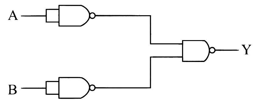
Logic Gates
The logic gate combination circuit shown in the figure performs the logic function of
(a) OR gate (b) NOR gate (c) XOR gate (d) NAND gate Show answer and solution
Answer: (c)
Loading the solution…
Report a mistake Q80 MHT CET 2024 · 2 MAY · SHIFT 1 Medium ☆
Logic Gates
The logic circuit in figure is equivalent to
(a) OR gate (b) AND gate (c) NOR gate (d) NAND gate Show answer and solution
Answer: (d)
Loading the solution…
Report a mistake Q81 NEET 2024 Medium ☆
Logic Gates
The output ( Y Y Y
(a) NAND gate (b) NOR gate (c) OR gate (d) AND gate Show answer and solution
Answer: (d)
Loading the solution…
Report a mistake Q82 JEE Main 2024 · 4 APR · SHIFT 2 Medium ☆
Logic Gates
Identify the logic gate given in the circuit:
(a) OR gate (b) NAND gate (c) NOR gate (d) AND gate Show answer and solution
Answer: (a)
Loading the solution…
Report a mistake Q83 JEE Main 2024 · 31 JAN · SHIFT 1 Medium ☆
Logic Gates
Identify the logic operation performed by the given circuit.
Show answer and solution
Answer: (c)
Loading the solution…
Report a mistake Q84 MHT CET 2023 · 13 MAY · SHIFT 1 Easy ☆
Logic Gates
If two inputs of a NAND gate are shorted, the resulting gate is
(a) an OR gate (b) an AND gate (c) a NOT gate (d) a NOR gate Show answer and solution
Answer: (c)
Loading the solution…
Report a mistake Q85 MHT CET 2023 · 11 MAY · SHIFT 1 Easy ☆
Logic Gates
In the case of NAND gate, if A and B are the inputs and Y \mathrm{Y} Y
(a) Y = A ⋅ B \mathrm{Y} = \mathrm{A} \cdot \mathrm{B} Y = A ⋅ B (b) Y = A − B ‾ \mathrm{Y} = \overline{\mathrm{A} - \mathrm{B}} Y = A − B (c) Y = A + B ‾ \mathrm{Y} = \overline{\mathrm{A} + \mathrm{B}} Y = A + B (d) Y = A ⋅ B ‾ \mathrm{Y} = \overline{\mathrm{A} \cdot \mathrm{B}} Y = A ⋅ B Show answer and solution
Answer: (d)
Loading the solution…
Report a mistake Q86 MHT CET 2023 · 10 MAY · SHIFT 2 Medium ☆
Logic Gates
The output of an 'OR' gate is connected to both the inputs of a 'NAND' gate. The combination will serve as
(a) OR gate (b) NOT gate (c) NOR gate (d) AND gate Show answer and solution
Answer: (c)
Loading the solution…
Report a mistake Q87 JEE Main 2023 · 13 APR · SHIFT 2 Medium ☆
Logic Gates
The output from NAND gate having inputs A and B given below will be,
Show answer and solution
Answer: (b)
Loading the solution…
Report a mistake Q88 MHT CET 2023 · 14 MAY · SHIFT 2 Medium ☆
Logic Gates
The output of following combination is same as that of
(a) AND gate (b) OR gate (c) NAND gate (d) NOR gate Show answer and solution
Answer: (d)
Loading the solution…
Report a mistake Q89 MHT CET 2023 · 13 MAY · SHIFT 2 Medium ☆
Logic Gates
The Boolean expression for the following combination is
(a) ( A + B ‾ ) ⋅ ( A + B ) (\overline{A + B}) \cdot (A + B) ( A + B ) ⋅ ( A + B ) (b) ( A ⋅ B ‾ ) + ( A ˉ ⋅ B ) (\overline{A \cdot B}) + (\bar{A} \cdot B) ( A ⋅ B ) + ( A ˉ ⋅ B ) (c) ( A ˉ ⋅ B ) + ( A ⋅ B ˉ ) (\bar{A} \cdot B) + (A \cdot \bar{B}) ( A ˉ ⋅ B ) + ( A ⋅ B ˉ ) (d) ( A ˉ + B ) ⋅ ( A + B ˉ ) (\bar{A} + B) \cdot (A + \bar{B}) ( A ˉ + B ) ⋅ ( A + B ˉ ) Show answer and solution
Answer: (c)
Loading the solution…
Report a mistake Q90 MHT CET 2023 · 12 MAY · SHIFT 2 Medium ☆
Logic Gates
In the following digital logic circuit, the output Y will be '1' for inputs
(a) A = 0, B = 0 (b) A = 0, B = 1 (c) A = 1, B = 0 (d) A = 1, B = 1 Show answer and solution
Answer: (d)
Loading the solution…
Report a mistake Q91 MHT CET 2023 · 11 MAY · SHIFT 2 Medium ☆
Logic Gates
In the digital circuit the inputs are as shown in figure. The Boolean expression for output Y \mathrm{Y} Y
(a) A + B ‾ + C ‾ \overline{\mathrm{A} + \mathrm{B}} + \overline{\mathrm{C}} A + B + C (b) A ⋅ B ‾ ⋅ C ‾ \overline{\mathrm{A} \cdot \mathrm{B}} \cdot \overline{\mathrm{C}} A ⋅ B ⋅ C (c) A ⋅ B ‾ + C ‾ \overline{\mathrm{A} \cdot \mathrm{B}} + \overline{\mathrm{C}} A ⋅ B + C (d) A + B ‾ ⋅ C ‾ \overline{\mathrm{A} + \mathrm{B}} \cdot \overline{\mathrm{C}} A + B ⋅ C Show answer and solution
Answer: (c)
Loading the solution…
Report a mistake Q92 MHT CET 2023 · 10 MAY · SHIFT 1 Medium ☆
Logic Gates
To obtain the truth-table shown, from the following logic circuit, the gate G should be
Show answer and solution
Answer: (d)
Loading the solution…
Report a mistake Q93 MHT CET 2023 · 9 MAY · SHIFT 1 Medium ☆
Logic Gates
To get the truth table shown, from the following logic circuit, the Gate G should be
Show answer and solution
Answer: (b)
Loading the solution…
Report a mistake Q94 NEET 2023 Medium ☆
Logic Gates
For the following logic circuit, the truth table is:
Show answer and solution
Answer: (a)
Loading the solution…
Report a mistake Q95 JEE Main 2023 · 13 APR · SHIFT 1 Medium ☆
Logic Gates
For the following circuit and given inputs A and B, choose the correct option for output 'Y Y Y
Show answer and solution
Answer: (d)
Loading the solution…
Report a mistake Q96 JEE Main 2023 · 30 JAN · SHIFT 2 Medium ☆
Logic Gates
The output Y Y Y A A A B B B
Truth table of the shown circuit is:
Show answer and solution
Answer: (a)
Loading the solution…
Report a mistake Q97 JEE Main 2023 · 29 JAN · SHIFT 2 Medium ☆
Logic Gates
For the given logic gates combination, the correct truth table will be
Show answer and solution
Answer: (d)
Loading the solution…
Report a mistake Q98 MHT CET 2023 · 12 MAY · SHIFT 1 Medium ☆
Logic Gates
The following logic gate combination is equivalent to
(a) NAND gate (b) OR gate (c) XOR gate (d) NOT gate Show answer and solution
Answer: (c)
Loading the solution…
Report a mistake Q99 MHT CET 2023 · 12 MAY · SHIFT 1 Medium ☆
Logic Gates
The logic gate combination circuit shown in the figure performs the logic function of
(a) AND gate (b) NAND gate (c) OR gate (d) XOR gate Show answer and solution
Answer: (a)
Loading the solution…
Report a mistake Q100 NEET 2023 Medium ☆
Logic Gates
The given circuit is equivalent to:
Show answer and solution
Answer: (d)
Loading the solution…
Report a mistake Q101 JEE Main 2023 · 11 APR · SHIFT 2 Medium ☆
Logic Gates
The logic operations performed by the given digital circuit is equivalent to:
Show answer and solution
Answer: (b)
Loading the solution…
Report a mistake Q102 JEE Main 2023 · 11 APR · SHIFT 1 Medium ☆
Logic Gates
The logic performed by the circuit shown in figure is equivalent to:
Show answer and solution
Answer: (b)
Loading the solution…
Report a mistake Q103 JEE Main 2023 · 6 APR · SHIFT 1 Medium ☆
Logic Gates
Name the logic gate equivalent to the diagram attached
Show answer and solution
Answer: (a)
Loading the solution…
Report a mistake Q104 JEE Main 2023 · 24 JAN · SHIFT 2 Medium ☆
Logic Gates
The logic gate equivalent to the given circuit diagram is:
Show answer and solution
Answer: (c)
Loading the solution…
Report a mistake Q105 JEE Main 2023 · 8 APR · SHIFT 1 Medium ☆
Logic Gates
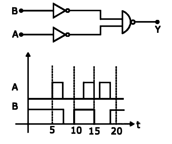
For the logic circuit shown, the output waveform at Y \mathrm{Y} Y
Show answer and solution
Answer: (b)
Loading the solution…
Report a mistake Q106 JEE Main 2023 · 30 JAN · SHIFT 1 Medium ☆
Logic Gates
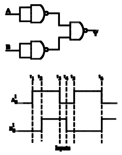
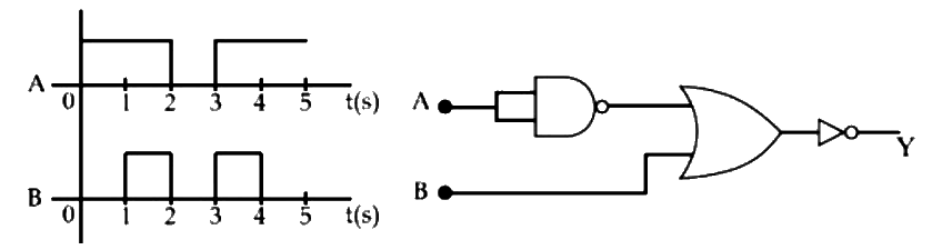
The output waveform of the given logical circuit for the following inputs A and B as shown below, is:
Show answer and solution
Answer: (d)
Loading the solution…
Report a mistake Q107 MHT CET 2022 · 11 AUG · SHIFT 2 Easy ☆
Logic Gates
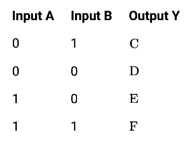
For a NAND gate, the inputs and outputs are given below.
The values taken by C, D, E, F are respectively
(a) 0, 1, 0, 0 (b) 1, 1, 1, 0 (c) 1, 0, 1, 1 (d) 0, 1, 0, 1 Show answer and solution
Answer: (b)
Loading the solution…
Report a mistake Q108 JEE Main 2022 · 27 JUL · SHIFT 1 Easy ☆
Logic Gates
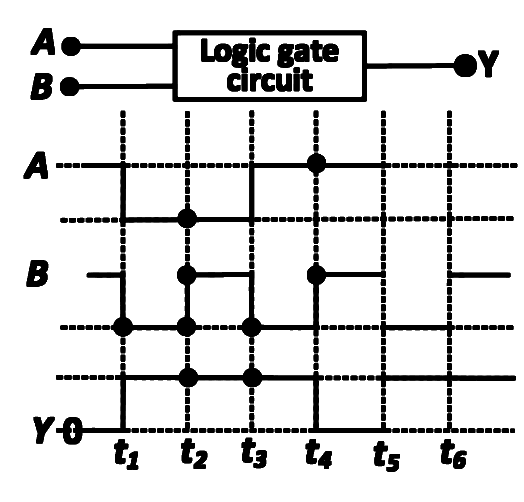
A logic gate circuit has two inputs A and B and output Y. The voltage waveforms of A, B and Y are shown below.
The logic gate circuit is:
(a) AND gate (b) OR gate (c) NOR gate (d) NAND gate Show answer and solution
Answer: (a)
Loading the solution…
Report a mistake Q109 NEET 2022 · PHASE 1 Medium ☆
Logic Gates
The truth table for the given logic circuit is
Show answer and solution
Answer: (c)
Loading the solution…
Report a mistake Q110 JEE Main 2022 · 25 JUL · SHIFT 1 Medium ☆
Logic Gates
In the circuit, the logical value of A = 1 A = 1 A = 1 B = 1 B = 1 B = 1 A A A B B B 5 V 5\text{ V} 5 V A = 0 A = 0 A = 0 B = 0 B = 0 B = 0 A A A B B B 0 V 0\text{ V} 0 V
The truth table of the given circuit will be:
(a) A B Y 0 0 0 1 0 0 0 1 0 1 1 1 A \quad B \quad Y \quad 0 \quad 0 \quad 0 \quad 1 \quad 0 \quad 0 \quad 0 \quad 1 \quad 0 \quad 1 \quad 1 \quad 1 A B Y 0 0 0 1 0 0 0 1 0 1 1 1 (b) A B Y 0 0 0 1 0 1 0 1 1 1 1 1 A \quad B \quad Y \quad 0 \quad 0 \quad 0 \quad 1 \quad 0 \quad 1 \quad 0 \quad 1 \quad 1 \quad 1 \quad 1 \quad 1 A B Y 0 0 0 1 0 1 0 1 1 1 1 1 (c) A B Y 0 0 0 1 0 0 0 1 0 1 1 0 A \quad B \quad Y \quad 0 \quad 0 \quad 0 \quad 1 \quad 0 \quad 0 \quad 0 \quad 1 \quad 0 \quad 1 \quad 1 \quad 0 A B Y 0 0 0 1 0 0 0 1 0 1 1 0 (d) A B Y 0 0 1 1 0 1 0 1 1 1 1 0 A \quad B \quad Y \quad 0 \quad 0 \quad 1 \quad 1 \quad 0 \quad 1 \quad 0 \quad 1 \quad 1 \quad 1 \quad 1 \quad 0 A B Y 0 0 1 1 0 1 0 1 1 1 1 0 Show answer and solution
Answer: (a)
Loading the solution…
Report a mistake Q111 JEE Main 2022 · 28 JUN · SHIFT 1 Medium Old syllabus ☆
Logic Gates
In the following circuit, the correct relation between output (Y) and inputs A and B will be:
(a) Y = AB (b) Y = A + B (c) Y = A B ‾ Y = \overline{AB} Y = A B (d) Y = A + B ‾ Y = \overline{A + B} Y = A + B Show answer and solution
Answer: (c)
Loading the solution…
Report a mistake Q112 NEET 2022 · PHASE 2 Medium ☆
Logic Gates
Identify the equivalent logic gate represented by the given circuit
Show answer and solution
Answer: (b)
Loading the solution…
Report a mistake Q113 JEE Main 2022 · 27 JUN · SHIFT 1 Medium ☆
Logic Gates
Identify the correct Logic Gate for the following output (Y) of two inputs A and B.
Show answer and solution
Answer: (b)
Loading the solution…
Report a mistake Q114 JEE Main 2022 · 25 JUN · SHIFT 2 Medium ☆
Logic Gates
Identify the logic operation performed by the given circuit:
(a) AND gate (b) OR gate (c) NOR gate (d) NAND gate Show answer and solution
Answer: (a)
Loading the solution…
Report a mistake Q115 MHT CET 2021 · 23 SEP · SHIFT 2 Easy ☆
Logic Gates
For a two input AND gate, the four entries are shown in the truth table. Identify the correct ones out of these ( A , B = (\mathrm{A}, \mathrm{B} = ( A , B = Y = \mathrm{Y} = Y =
(a) 1 and 2 only (b) 1, 2 and 3 only (c) 1, 3 and 4 only (d) 2 and 4 only Show answer and solution
Answer: (b)
Loading the solution…
Report a mistake Q116 MHT CET 2021 · 22 SEP · SHIFT 2 Easy ☆
Logic Gates
Which of the following gates will give an output '1' for the given inputs?
(a) II and III (b) I and IV (c) I and III (d) II and IV Show answer and solution
Answer: (d)
Loading the solution…
Report a mistake Q117 MHT CET 2021 · 20 SEP · SHIFT 2 Easy ☆
Logic Gates
The output of an 'OR' gate is 'one'
(a) only when both inputs are 'one'. (b) only when both inputs are 'zero'. (c) only when either input is 'zero'. (d) if either or both inputs are 'one'. Show answer and solution
Answer: (d)
Loading the solution…
Report a mistake Q118 MHT CET 2021 · 20 SEP · SHIFT 1 Easy ☆
Logic Gates
Two different logic gates moving output '0' for the inputs (0, 1) and then for (1, 0) are
(a) 'AND', 'NAND' (b) 'NAND', 'NOR' (c) 'OR', 'AND' (d) 'NOR', 'AND' Show answer and solution
Answer: (d)
Loading the solution…
Report a mistake Q119 MHT CET 2021 · 22 SEP · SHIFT 1 Easy ☆
Logic Gates
A logic gate which gives output 'HIGH' only when its two input terminals are at different logic levels with respect to each other is
(a) NOR gate (b) OR gate (c) AND gate (d) X-OR gate Show answer and solution
Answer: (d)
Loading the solution…
Report a mistake Q120 JEE Main 2021 · 26 AUG · SHIFT 2 Medium ☆
Logic Gates
Four NOR gates are connected as shown in figure. The truth table for the given figure is:
Show answer and solution
Answer: (d)
Loading the solution…
Report a mistake Q121 MHT CET 2021 · 24 SEP · SHIFT 1 Medium ☆
Logic Gates
For the output of the following logic circuit to be '1', the values of inputs A and B should be respectively
(a) 0 and 1 (b) 0 and 0 (c) 1 and 1 (d) 1 and 0 Show answer and solution
Answer: (b)
Loading the solution…
Report a mistake Q122 NEET 2021 Medium ☆
Logic Gates
For the given circuit, the input digital signals are applied at the terminals A, B and C. What would be the output at the terminal y?
Show answer and solution
Answer: (c)
Loading the solution…
Report a mistake Q123 JEE Main 2021 · 31 AUG · SHIFT 1 Medium ☆
Logic Gates
In the following logic circuit the sequence of the inputs A, B are (0, 0), (0, 1), (1, 0) and (1, 1). The output Y for this sequence will be:
(a) 1, 0, 1, 0 (b) 0, 1, 0, 1 (c) 1, 1, 1, 0 (d) 0, 0, 1, 1 Show answer and solution
Answer: (c)
Loading the solution…
Report a mistake Q124 JEE Main 2021 · 17 MAR · SHIFT 2 Medium ☆
Logic Gates
Which one of the following will be the output of the given circuit?
(a) XOR Gate (b) NOR Gate (c) NAND Gate (d) AND Gate Show answer and solution
Answer: (a)
Loading the solution…
Report a mistake Q125 JEE Main 2021 · 25 FEB · SHIFT 2 Medium ☆
Logic Gates
The truth table for the following logic circuit is:
Show answer and solution
Answer: (d)
Loading the solution…
Report a mistake Q126 JEE Main 2021 · 16 MAR · SHIFT 1 Medium ☆
Logic Gates
In the logic circuit shown in the figure, if input A and B are 0 and 1 respectively, the output at Y would be 'x'.
The value of x is ____________.
Numerical answer type. Work it out, then open the answer.
Show answer and solution
Answer: 0
Loading the solution…
Report a mistake Q127 MHT CET 2021 · 23 SEP · SHIFT 1 Medium ☆
Logic Gates
The resultant gate and its Boolean expression in the given circuit is
(a) NOR,A + B ‾ \overline{\mathrm{A} + \mathrm{B}} A + B (b) AND, A ⋅ B \mathrm{A} \cdot \mathrm{B} A ⋅ B (c) OR, A+B (d) NAND,A ⋅ B ‾ \overline{\mathrm{A} \cdot \mathrm{B}} A ⋅ B Show answer and solution
Answer: (b)
Loading the solution…
Report a mistake Q128 MHT CET 2021 · 21 SEP · SHIFT 2 Medium ☆
Logic Gates
Combination of NAND gates is shown in the figure. It is equivalent to
(a) AND gate (b) NOR gate (c) OR gate (d) X-OR gate Show answer and solution
Answer: (c)
Loading the solution…
Report a mistake Q129 JEE Main 2021 · 26 AUG · SHIFT 1 Medium ☆
Logic Gates
Identify the logic operation carried out by the given circuit :-
Show answer and solution
Answer: (c)
Loading the solution…
Report a mistake Q130 JEE Main 2021 · 27 JUL · SHIFT 2 Medium ☆
Logic Gates
Find the truth table for the function Y of A and B represented in the following figure.
Show answer and solution
Answer: (b)
Loading the solution…
Report a mistake Q131 JEE Main 2021 · 25 JUL · SHIFT 1 Medium ☆
Logic Gates
Identify the logic operation carried out.
Show answer and solution
Answer: (b)
Loading the solution…
Report a mistake Q132 JEE Main 2021 · 17 MAR · SHIFT 1 Medium ☆
Logic Gates
The output of the given combination gates represents:
(a) AND Gate (b) NOR Gate (c) NAND Gate (d) XOR Gate Show answer and solution
Answer: (c)
Loading the solution…
Report a mistake Q133 JEE Main 2021 · 16 MAR · SHIFT 2 Medium ☆
Logic Gates
The following logic gate is equivalent to:
(a) NOR Gate (b) NAND Gate (c) OR Gate (d) AND Gate Show answer and solution
Answer: (a)
Loading the solution…
Report a mistake Q134 JEE Main 2021 · 26 FEB · SHIFT 2 Medium ☆
Logic Gates
Draw the output signal Y in the given combination of gates.
Show answer and solution
Answer: (a)
Loading the solution…
Report a mistake Q135 JEE Main 2021 · 24 FEB · SHIFT 2 Medium ☆
Logic Gates
The logic circuit shown above is equivalent to:
Show answer and solution
Answer: (d)
Loading the solution…
Report a mistake Q136 JEE Main 2021 · 31 AUG · SHIFT 2 Medium Old syllabus ☆
Logic Gates
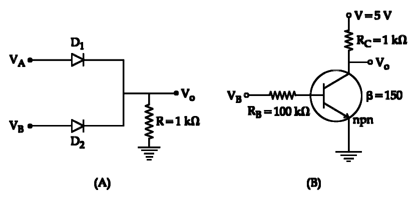
If VA and VB are the input voltages (either 5V or 0V) and V0 is the output voltage then the two gates represented in the following circuit (A) and (B) are :-
(a) AND and OR Gate (b) OR and NOT Gate (c) NAND and NOR Gate (d) AND and NOT Gate Show answer and solution
Answer: (b)
Loading the solution…
Report a mistake Q137 NEET 2020 · PHASE 2 Easy ☆
Logic Gates
Which of the following gate is called universal gate?
(a) NOT gate (b) OR gate (c) AND gate (d) NAND gate Show answer and solution
Answer: (d)
Loading the solution…
Report a mistake Q138 NEET 2020 · PHASE 1 Medium ☆
Logic Gates
For the logic circuit shown, the truth table is:
Show answer and solution
Answer: (d)
Loading the solution…
Report a mistake Q139 JEE Main 2020 · 2 SEP · SHIFT 2 Medium ☆
Logic Gates
In the following digital circuit, what will be the output at ‘Z’, when the
input (A, B) are (1, 0), (0, 0), (1, 1,), (0, 1)
(a) 1, 1, 0, 1 (b) 0, 1, 0, 0 (c) 1, 0, 1, 1 (d) 0, 0, 1, 0 Show answer and solution
Answer: (d)
Loading the solution…
Report a mistake Q140 JEE Main 2020 · 8 JAN · SHIFT 2 Medium ☆
Logic Gates
In the given circuit, value of Y is:
(a) toggles between 0 and 1 (b) 1 (c) will not execute (d) 0 Show answer and solution
Answer: (d)
Loading the solution…
Report a mistake Q141 JEE Main 2020 · 8 JAN · SHIFT 1 Medium ☆
Logic Gates
Boolean relation at the output stage-Y for the following circuit is:
(a) A.B (b) A ‾ + B ‾ \overline{A} + \overline{B} A + B (c) A ‾ . B ‾ \overline{A}.\overline{B} A . B (d) A + B Show answer and solution
Answer: (c)
Loading the solution…
Report a mistake Q142 JEE Main 2020 · 6 SEP · SHIFT 1 Medium ☆
Logic Gates
Identify the correct output signal Y in the given combination of gates (as shown) for the given inputs A and B.
Show answer and solution
Answer: (d)
Loading the solution…
Report a mistake Q143 JEE Main 2020 · 4 SEP · SHIFT 2 Medium ☆
Logic Gates
Identify the operation performed by the circuit given below:
Show answer and solution
Answer: (a)
Loading the solution…
Report a mistake Q144 JEE Main 2020 · 7 JAN · SHIFT 1 Difficult ☆
Logic Gates
Which of the following gives a reversible operation?
Show answer and solution
Answer: (b)
Loading the solution…
Report a mistake Q145 JEE Main 2019 · 12 APR · SHIFT 1 Medium ☆
Logic Gates
The truth table for the circuit given in the fig. is:
(a) B B B 0 1 1 0 1 1 0 \quad 1 \quad 1 \quad 0 \quad 1 \quad 1 0 1 1 0 1 1 (b) B B B 0 1 1 0 0 1 0 \quad 1 \quad 1 \quad 0 \quad 0 \quad 1 0 1 1 0 0 1 (c) B B B 0 1 1 0 0 1 0 \quad 1 \quad 1 \quad 0 \quad 0 \quad 1 0 1 1 0 0 1 (d) B B B 0 1 0 1 0 \quad 1 \quad 0 \quad 1 0 1 0 1 Show answer and solution
Answer: (c)
Loading the solution…
Report a mistake Q146 JEE Main 2019 · 12 JAN · SHIFT 1 Medium ☆
Logic Gates
The output of the given logic circuit is:
(a) A ‾ B \overline{A}B A B (b) A B + A B ‾ AB + \overline{AB} A B + A B (c) A B ‾ + A ‾ B A\overline{B} + \overline{A}B A B + A B (d) A B ‾ A\overline{B} A B Show answer and solution
Answer: (d)
Loading the solution…
Report a mistake Q147 JEE Main 2019 · 10 JAN · SHIFT 1 Medium ☆
Logic Gates
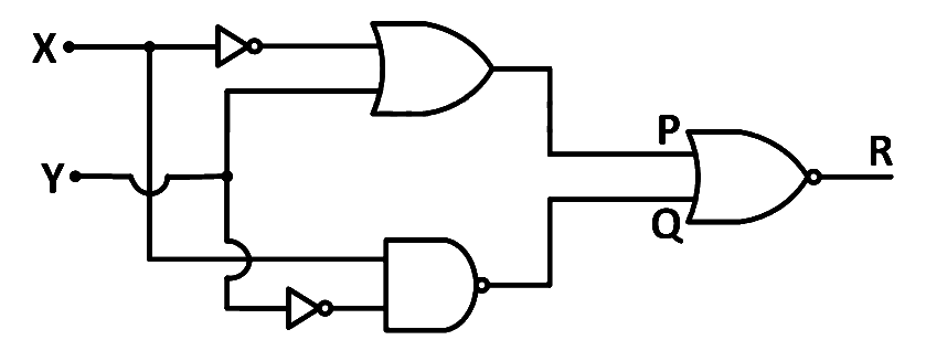
To get output 1 at R, for the given logic gate circuit the input values must be
(a) x = 0, y = 0 (b) x = 1, y = 0 (c) x = 0, y = 1 (d) x = 1, y = 1 Show answer and solution
Answer: (b)
Loading the solution…
Report a mistake Q148 NEET 2019 Medium ☆
Logic Gates
The circuit diagram shown here corresponds to the logic gate,
Show answer and solution
Answer: (b)
Loading the solution…
Report a mistake Q149 NEET 2019 Medium ☆
Logic Gates
The correct Boolean operation represented by the circuit diagram drawn is:
Show answer and solution
Answer: (b)
Loading the solution…
Report a mistake Q150 JEE Main 2019 · 9 APR · SHIFT 2 Medium ☆
Logic Gates
The logic gate equivalent to the given logic circuit is :-
Show answer and solution
Answer: (d)
Loading the solution…
Report a mistake Q151 NEET 2018 Medium ☆
Logic Gates
In the combination of the following gates the output Y can be written in terms of inputs A and B as
(a) A . B ‾ \overline{A.B} A . B (b) A . B ‾ + A ‾ . B A.\overline{B} + \overline{A}.B A . B + A . B (c) A . B ‾ + A . B \overline{A.B} + A.B A . B + A . B (d) A + B ‾ \overline{A + B} A + B Show answer and solution
Answer: (b)
Loading the solution…
Report a mistake Q152 JEE Main 2018 · 15 APR · SHIFT 2 Medium ☆
Logic Gates
Truth table for the following digital circuit will be:
Show answer and solution
Answer: (c)
Loading the solution…
Report a mistake Q153 NEET 2017 Medium ☆
Logic Gates
The given electrical network is equivalent to
(a) OR gate (b) NOR gate (c) NOT gate (d) AND gate Show answer and solution
Answer: (b)
Loading the solution…
Report a mistake Q154 JEE Main 2016 · 9 APR · SHIFT 1 Easy ☆
Logic Gates
The truth table given in fig. represents:
(a) AND - Gate (b) OR - Gate (c) NAND - Gate (d) NOR - Gate Show answer and solution
Answer: (b)
Loading the solution…
Report a mistake Q155 NEET 2016 · PHASE 2 Medium ☆
Logic Gates
What is the output Y in the following circuit, when all the three inputs A, B, C are first 0 and then 1?
(a) 0, 1 (b) 0, 0 (c) 1, 0 (d) 1, 1 Show answer and solution
Answer: (c)
Loading the solution…
Report a mistake Q156 NEET 2016 · PHASE 1 Medium ☆
Logic Gates
To get output 1 for the following circuit, the correct choice for the input is
(a) A = 1, B = 1, C = 0 (b) A = 1, B = 0, C = 1 (c) A = 0, B = 1, C = 0 (d) A = 1, B = 0, C = 0 Show answer and solution
Answer: (b)
Loading the solution…
Report a mistake Q157 JEE Main 2016 · 10 APR · SHIFT 1 Medium ☆
Logic Gates
To get an output of 1 from the circuit shown in figure the input must be:
(a) a = 0, b = 1, c = 0 (b) a = 1, b = 0, c = 0 (c) a = 1, b = 0, c = 1 (d) a = 0, b = 0, c = 1 Show answer and solution
Answer: (c)
Loading the solution…
Report a mistake Q158 JEE Main 2016 Medium ☆
Logic Gates
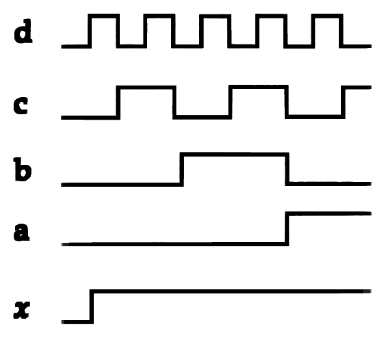
If a , b , c , d a, b, c, d a , b , c , d x x x
(a) O R OR OR (b) N A N D NAND N A N D (c) N O T NOT NOT (d) A N D AND A N D Show answer and solution
Answer: (a)
Loading the solution…
Report a mistake Q159 NEET 2015 · AIPMT · CANCELLED PAPER Medium ☆
Logic Gates
Which logic gate is represented by the following combination of logic gates?
Show answer and solution
Answer: (a)
Loading the solution…
Report a mistake Q160 JEE Main 2014 · 9 APR · SHIFT 1 Easy ☆
Logic Gates
Identify the gate and match A, B, Y in bracket to check.
(a) AND ( A= 1, B = 1, Y = 1) (b) OR (A = 1, B = 1, Y = 0) (c) NOT (A = 1, B = 1, Y = 1) (d) XOR (A = 0, B = 0, Y = 0) Show answer and solution
Answer: (a)
Loading the solution…
Report a mistake Q161 JEE Main 2014 · 19 APR · SHIFT 1 Medium ☆
Logic Gates
Given: A and B are input terminals.
Logic 1 = > 5 V
Logic 0 = < 1 V
Which logic gate operation, the following circuit does?
(a) AND Gate (b) OR Gate (c) XOR Gate (d) NOR Gate Show answer and solution
Answer: (a)
Loading the solution…
Report a mistake Q162 NEET 2013 Easy ☆
Logic Gates
The output from a NAND gate is divided into two in parallel and fed to another NAND gate. The resulting gate is a
(a) AND gate (b) NOR gate (c) OR gate (d) NOT gate Show answer and solution
Answer: (a)
Loading the solution…
Report a mistake Q163 NEET 2013 Medium ☆
Logic Gates
The output (X) of the logic circuit shown in figure will be
(a) X = A. B (b) X =A + B ‾ \overline{A + B} A + B (c) X =A . B ‾ ‾ \overline{\overline{A.B}} A . B (d) X =A . B ‾ \overline{A.B} A . B Show answer and solution
Answer: (a)
Loading the solution…
Report a mistake Q164 JEE Main 2013 · 25 APR · SHIFT 1 Medium ☆
Logic Gates
Which of the following circuits correctly represents the following truth table?
Show answer and solution
Answer: (a)
Loading the solution…
Report a mistake Q165 JEE Main 2013 · 23 APR · SHIFT 1 Medium ☆
Logic Gates
A system of four gates is set up as shown. The 'truth table' corresponding to this system is:
Show answer and solution
Answer: (a)
Loading the solution…
Report a mistake Q166 JEE Main 2013 · 9 APR · SHIFT 1 Difficult ☆
Logic Gates
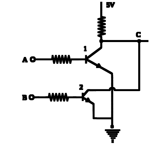
Consider two npn transistors as shown in the figure. If 0 Volts corresponds to false and 5 Volts correspond to true, then the output at C corresponds to:
(a) A NAND B (b) A OR B (c) A AND B (d) A NOR B Show answer and solution
Answer: (d)
Loading the solution…
Report a mistake Q167 NEET 2012 · AIPMT · PRELIMS Easy ☆
Logic Gates
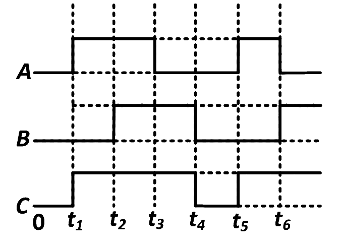
The figure shows a logic circuit with two inputs A and B and the output C. The voltage wave forms across A, B and C are as given. The logic circuit gate is
(a) OR gate (b) NOR gate (c) AND gate (d) NAND gate Show answer and solution
Answer: (a)
Loading the solution…
Report a mistake Q168 NEET 2012 · AIPMT · MAINS Medium ☆
Logic Gates
To get an output Y= 1 in given circuit which of the following input will be correct?
(a) A → \rightarrow → → \rightarrow → → \rightarrow → (b) A → \rightarrow → → \rightarrow → → \rightarrow → (c) A → \rightarrow → → \rightarrow → → \rightarrow → (d) A → \rightarrow → → \rightarrow → → \rightarrow → Show answer and solution
Answer: (b)
Loading the solution…
Report a mistake Q169 JEE Main 2012 · AIEEE Medium ☆
Logic Gates
Truth table for system of four N A N D NAND N A N D
Show answer and solution
Answer: (a)
Loading the solution…
Report a mistake Q170 NEET 2011 · AIPMT · PRELIMS Easy ☆
Logic Gates
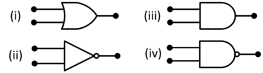
Symbolic representation of four logic gates are shown as
Pick out which ones are for AND, NAND and NOT gates, respectively
(a) (ii), (iii) and (iv) (b) (iii), (ii) and (i) (c) (iii), (ii) and (iv) (d) (iii), (iv) and (ii) Show answer and solution
Answer: (d)
Loading the solution…
Report a mistake Q171 NEET 2010 · AIPMT · MAINS Easy ☆
Logic Gates
The following figure shows a logic gate circuit with two inputs A and B and the output Y. The voltage waveforms of A, B and Y are as given.
The logic gate is
(a) NOR gate (b) OR gate (c) AND gate (d) NAND gate Show answer and solution
Answer: (d)
Loading the solution…
Report a mistake Q172 NEET 2010 · AIPMT · PRELIMS Medium ☆
Logic Gates
To get an output Y = 1 in given circuit which of the following input will be correct?
(a) A → \rightarrow → → \rightarrow → → \rightarrow → (b) A → \rightarrow → → \rightarrow → → \rightarrow → (c) A → \rightarrow → → \rightarrow → → \rightarrow → (d) A → \rightarrow → → \rightarrow → → \rightarrow → Show answer and solution
Answer: (b)
Loading the solution…
Report a mistake Q173 JEE Main 2010 · AIEEE Medium ☆
Logic Gates
The combination of gates shown below yields
(a) OR gate (b) NOT gate (c) XOR gate (d) NAND gate Show answer and solution
Answer: (a)
Loading the solution…
Report a mistake Q174 NEET 2009 · AIPMT Easy ☆
Logic Gates
The symbolic representation of four logic gates are given below
The logic symbols for OR, NOT and NAND gates are respectively
(a) (iv), (i), (iii) (b) (iv), (ii), (i) (c) (i), (iii), (iv) (d) (iii), (iv), (ii) Show answer and solution
Answer: (b)
Loading the solution…
Report a mistake Q175 JEE Main 2009 · AIEEE Medium ☆
Logic Gates
The logic circuit shown below has the input waveforms ’ A ’ \text{'}A\text{'} ’ A ’ ’ B ’ \text{'}B\text{'} ’ B ’
Output is
Show answer and solution
Answer: (d)
Loading the solution…
Report a mistake Q176 JEE Main 2008 · AIEEE Medium ☆
Logic Gates
In the circuit below, A A A B B B C C C
The circuit represents
(a) NOR gate (b) AND gate (c) NAND gate (d) OR gate Show answer and solution
Answer: (d)
Loading the solution…
Report a mistake Q177 NEET 2008 · AIPMT Medium ☆
Logic Gates
The circuit is equivalent to
(a) NOR gate (b) OR gate (c) AND gate (d) NAND gate Show answer and solution
Answer: (a)
Loading the solution…
Report a mistake Q178 NEET 2007 · AIPMT Medium ☆
Logic Gates
In the following circuit, the output Y for all possible inputs A and B is expressed by the truth table.
(a) A B Y 0 0 0 1 0 0 0 1 0 1 1 1 A \quad B \quad Y \quad 0 \quad 0 \quad 0 \quad 1 \quad 0 \quad 0 \quad 0 \quad 1 \quad 0 \quad 1 \quad 1 \quad 1 A B Y 0 0 0 1 0 0 0 1 0 1 1 1 (b) A B Y 0 0 1 0 1 0 1 0 0 1 1 0 A \quad B \quad Y \quad 0 \quad 0 \quad 1 \quad 0 \quad 1 \quad 0 \quad 1 \quad 0 \quad 0 \quad 1 \quad 1 \quad 0 A B Y 0 0 1 0 1 0 1 0 0 1 1 0 (c) A B Y 0 0 0 0 1 1 1 0 1 1 1 1 A \quad B \quad Y \quad 0 \quad 0 \quad 0 \quad 0 \quad 1 \quad 1 \quad 1 \quad 0 \quad 1 \quad 1 \quad 1 \quad 1 A B Y 0 0 0 0 1 1 1 0 1 1 1 1 (d) A B Y 0 0 1 1 0 1 0 1 1 1 1 0 A \quad B \quad Y \quad 0 \quad 0 \quad 1 \quad 1 \quad 0 \quad 1 \quad 0 \quad 1 \quad 1 \quad 1 \quad 1 \quad 0 A B Y 0 0 1 1 0 1 0 1 1 1 1 0 Show answer and solution
Answer: (c)
Loading the solution…
Report a mistake Q179 NEET 2006 · AIPMT Easy ☆
Logic Gates
The following figure shows a logic gate circuit with two inputs A and B and the output C.
The voltage waveforms of A, B and C are as shown below.
The logic circuit gate is
(a) OR gate (b) AND gate (c) NAND gate (d) NOR gate Show answer and solution
Answer: (b)
Loading the solution…
Report a mistake Q180 NEET 2004 · AIPMT Easy ☆
Logic Gates
The output of OR gate is 1
(a) if both inputs are zero (b) if either or both inputs are 1 (c) only if both inputs are 1 (d) if either inputs is zero Show answer and solution
Answer: (b)
Loading the solution…
Report a mistake Q181 NEET 2003 · AIPMT Medium ☆
Logic Gates
Following diagram performs the logic function of
(a) OR gate (b) AND gate (c) XOR gate (d) NAND gate Show answer and solution
Answer: (b)
Loading the solution…
Report a mistake Q182 NEET 2002 · AIPMT Easy ☆
Logic Gates
The given truth table is for which logic gate
A B Y A \quad B \quad Y A B Y
1 1 0 1 \quad 1 \quad 0 1 1 0
0 1 1 0 \quad 1 \quad 1 0 1 1
1 0 1 1 \quad 0 \quad 1 1 0 1
0 0 1 0 \quad 0 \quad 1 0 0 1
(a) NAND (b) XOR (c) NOR (d) OR. Show answer and solution
Answer: (a)
Loading the solution…
Report a mistake Q183 NEET 2001 · AIPMT Easy ☆
Logic Gates
The given truth table is for which logic gate
A B Y A \quad B \quad Y A B Y
1 1 0 1 \quad 1 \quad 0 1 1 0
0 1 1 0 \quad 1 \quad 1 0 1 1
1 0 1 1 \quad 0 \quad 1 1 0 1
0 0 1 0 \quad 0 \quad 1 0 0 1
Show answer and solution
Answer: (a)
Loading the solution…
Report a mistake Q184 NEET 2000 · AIPMT Easy ☆
Logic Gates
The truth table given below
represents
(a) AND gate (b) NOR gate (c) OR gate (d) NAND gate Show answer and solution
Answer: (a)
Loading the solution…
Report a mistake Q185 NEET 1999 · AIPMT Medium ☆
Logic Gates
The following circuit represents
(a) OR gate (b) XOR gate (c) AND gate (d) NAND gate Show answer and solution
Answer: (b)
Loading the solution…
Report a mistake Q186 NEET 1998 · AIPMT Easy ☆
Logic Gates
Which one of the following gates will have an output of 1?
Show answer and solution
Answer: (c)
Loading the solution…
Report a mistake Q187 NEET 1998 · AIPMT Easy ☆
Logic Gates
The truth table given below is for which gate?
Show answer and solution
Answer: (d)
Loading the solution…
Report a mistake Q188 NEET 1997 · AIPMT Easy ☆
Logic Gates
The following truth-table belongs to which one of the following four gates?
Show answer and solution
Answer: (b)
Loading the solution…
Report a mistake Q189 NEET 1996 · AIPMT Easy ☆
Logic Gates
This symbol represents
(a) AND gate (b) NOR gate (c) NAND gate (d) OR gate Show answer and solution
Answer: (c)
Loading the solution…
Report a mistake Q190 NEET 1995 · AIPMT Easy ☆
Logic Gates
The following truth-table belongs to which one of the following four gates?
Show answer and solution
Answer: (b)
Loading the solution…
Report a mistake Q191 NEET 1994 · AIPMT Easy ☆
Logic Gates
The given truth table is for which logic gate?
Show answer and solution
Answer: (a)
Loading the solution…
Report a mistake Q192 NEET 1991 · AIPMT Easy ☆
Logic Gates
The following truth table corresponds to the logical gate
Show answer and solution
Answer: (b)
Loading the solution…
Report a mistake
No questions match these filters.